
Structures constructed using coal combustion materials

a technology of combustion materials and structures, applied in the direction of natural mineral layered products, solid waste management, water-setting substance layered products, etc., can solve the problems of increasing the negative view of the manner in which ccr's are stored, reducing strength, and requiring expense in storing materials, etc., to achieve low leaching, increase the fill rate of the lock system, and low permeability

Active Publication Date: 2018-06-05
GO TEAM CCR LLC
View PDF123 Cites 1 Cited by
  • Summary
  • Abstract
  • Description
  • Claims
  • Application Information

AI Technical Summary

Benefits of technology

[0048]It is therefore one object of the invention to provide a means by which CCR can be used in beneficial ways to create structures that would otherwise use other, more expensive or non-renewable resources.
[0062]According to another embodiment of the invention, the beneficial use structure is a carbon sequestration / mineral carbonation facility that includes a containment enclosure including a base having tapered walls constructed of strengthened CCR in a mixture with materials that fill interstices between the CCR particles with material that is stable and does not permit leakage of sequestered material from the facility. A plurality of sequestration beds are positioned within the enclosure, and a two stage filter section is provided that includes a first stage with a relatively coarse filtration material and a second filter section with a relatively fine filtration material adapted to provide a progressive filtration effect across a large surface area to remove particulates and gas components of pressurized coal plant emissions that are injected into the containment enclosure through supply conduits. Vents communicate with the sequestration beds to allow filtered gases to be vented from the sequestration beds.
[0063]According to another embodiment of the invention, the beneficial use structure is a pumped hydroelectric facility adapted for use with a lock system of a waterway and includes a base constructed of compacted CCR and positioned on a terrain for increasing the elevation of the hydroelectric facility about the lock system of the waterway. A water impoundment having raised walls constructed of a material is provided and selected from the group consisting of compacted concrete and compacted low leaching and low permeability strengthened CCR. A lock filling piping system is provided that interconnects the water impoundment with the lock system of the waterway for increasing the fill rate of the lock system to permit an increased rate of transit of vessels through the lock system. Intake pipes are positioned upstream of the lock system for receiving water from the waterway, and a hydroelectric generator / pump facility is provided for receiving water from the intake pipes and generating electricity from movement of the water from the intakes pipes through the hydroelectric generator / pump facility.
[0064]According to another embodiment of the invention, the hydroelectric generator / pump facility is connected to impoundment fill piping for receiving water from the waterway and pumping the water into the impoundment for storage and use for increasing the fill rate of the lock system.

Problems solved by technology

CCR accumulates in vast quantities, and storing the material requires expense and creates environmental risk.
In recent years, regulatory authorities have taken an increasingly negative view of the manner in which CCR's are stored and have enacted regulations that will require that CCR's be handled in a manner different from past practice.
A higher percentage of fly ash can result in reduced strength.
Accordingly, a limiting factor may be the load bearing capabilities of the CCR and RCC structure when evaluated using conventional geotechnical design and slope stability evaluation methods.

Method used


Image

  • Structures constructed using coal combustion materials
  • Structures constructed using coal combustion materials
  • Structures constructed using coal combustion materials

Examples


Embodiment Construction

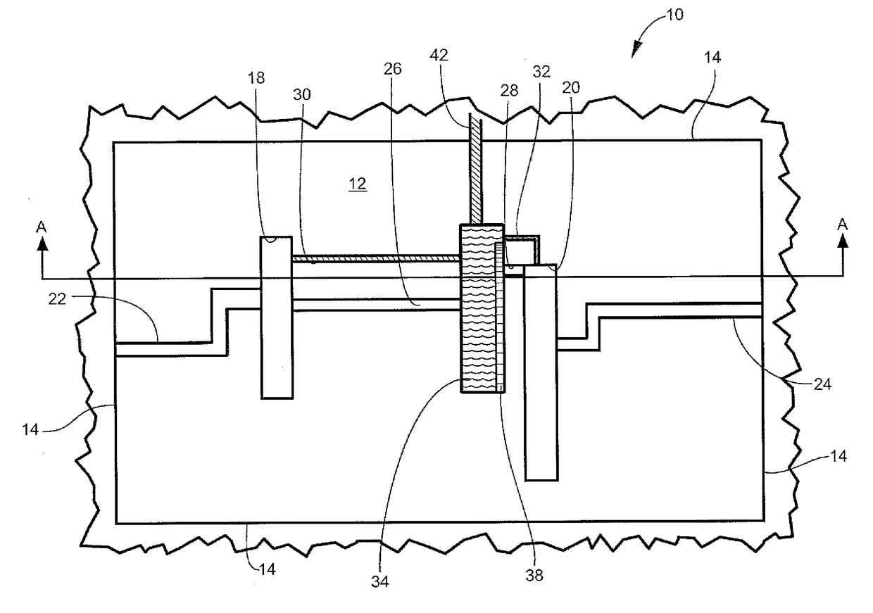
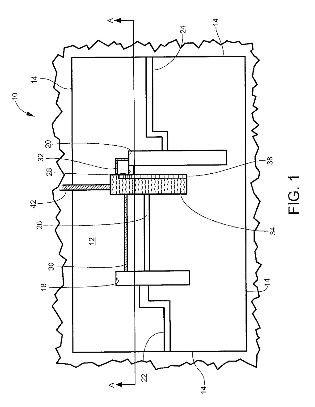
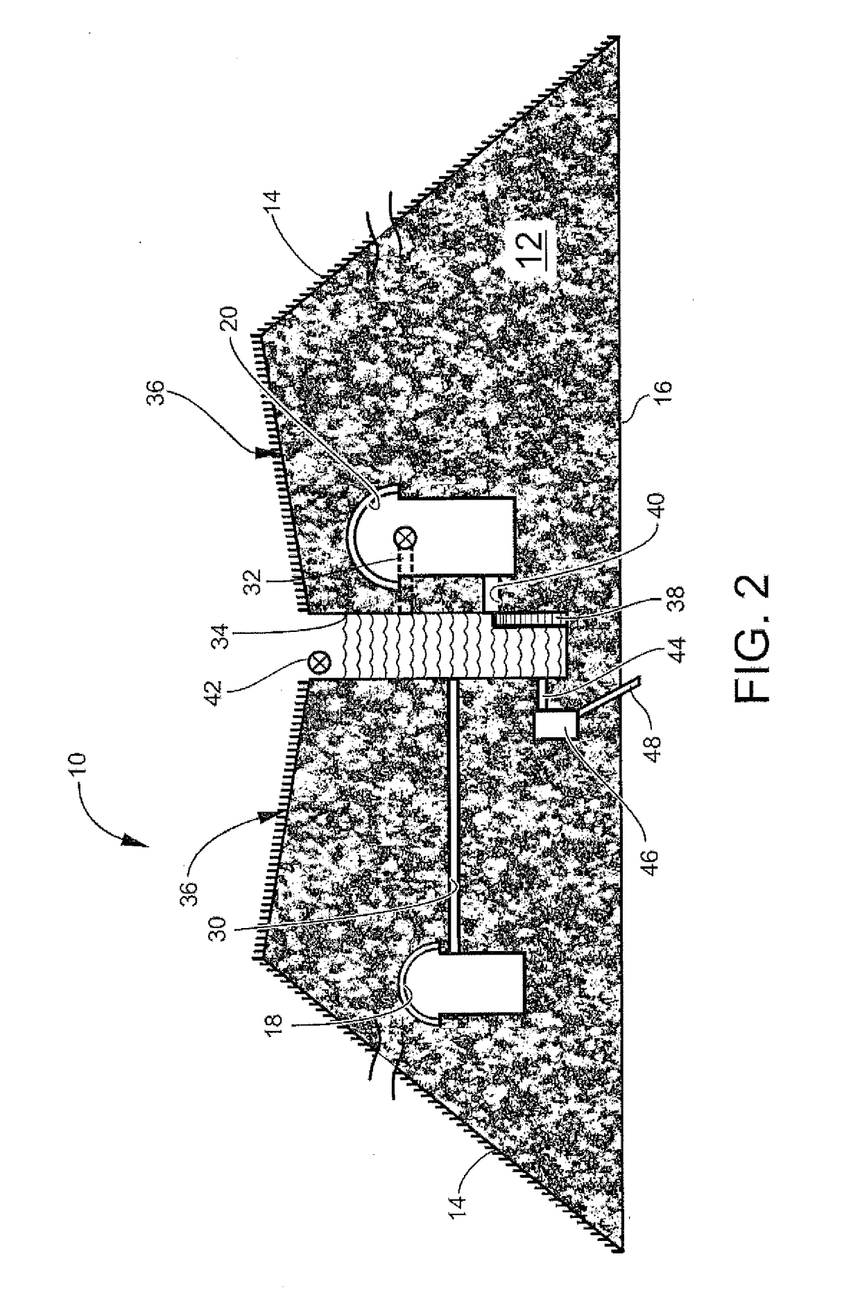
[0082]Referring now to the drawings, a survival bunker 10 with stepwell according to one preferred embodiment of the invention is illustrated in FIGS. 1 and 2. This embodiment is only an example of a wide variety of structures that can be fabricated using the techniques disclosed in this application, and is not drawn to scale. Bunker 10 includes an interior volume 12 defined by sloped sidewalls 14 and a planar top 36 that together define a truncated pyramid structure, which may or may not include inherent blast-deflecting characteristics.

[0083]The solid volume of the bunker 10 is formed of CCR-based materials according to the examples provided in this application. The bunker 10 is supported on a base 16, which will typically comprise the existing ground. The bunker 10 includes survival condominiums 18 and 20, which are comprised of a predetermined number of living areas. The condominiums 18 and 20 are reached by respective entrance / exit tunnels 22, 24 formed through the CCR material...


PUM

PropertyMeasurementUnit
compressive strengthaaaaaaaaaa
thicknessaaaaaaaaaa
solid volume thicknessaaaaaaaaaa

Abstract

Beneficial use structures are disclosed that include coal combustion residuals (“CCR”) mixed with water and a binder to form a structural material and adapted to be compacted for use in the formation of the beneficial use structure. Various structures having beneficial uses described, including survival bunkers, composting pits, mine reclamation encapsulation and carbon sequestration facilities, water storage facilities, compressed air storage facilities, carbon sequestration / mineral carbonation facilities and a pumped hydroelectric facility adapted for use with a lock system of a waterway.

Description

CROSS-REFERENCE TO RELATED APPLICATIONS AND PRIORITY[0001]This present application claims priority from and incorporates by reference the full contents of a provisional patent application filed on Aug. 16, 2016, Application No. 62 / 375,581, and U.S. patent application Ser. No. 15 / 416,460 filed on Jan. 26, 2017, now U.S. Pat. No. 9,790,703 and is a continuation-in-part of U.S. patent application Ser. No. 15 / 416,460 filed Jan. 26, 2017.TECHNICAL FIELD AND BACKGROUND OF THE INVENTION[0002]This invention relates to novel uses of a material known as “coal combustion residual” (“CCR”). CCR is finely comminuted particles of material that remain after coal has been burned to provide the immense quantities of heat required to operate high-pressure steam boilers in coal-fired electric power plants operated by electric power utilities such as the Tennessee Valley Authority, Duke Energy and others. CCR accumulates in vast quantities, and storing the material requires expense and creates environm...

Claims


Application Information

Patent Timeline
Patent Type & Authority Patents(United States)
IPC IPC(8): E04B1/00C04B18/06B28B3/12C04B18/08C04B28/02C04B40/00C04B111/00
CPCC04B40/0071B28B3/12C04B18/061C04B18/064C04B18/067C04B28/021C04B18/08C04B2111/00775C04B2111/00051C04B2111/00068C04B2111/00637C04B2111/00724B32B13/04B32B1/02C04B28/02C04B18/065E04H5/02E04H7/20E04H9/04E04H9/06E04C5/08F41H5/24F24F7/04B28B19/00B28B23/0081B28B23/0087B32B19/00C04B16/08C04B16/082C04B16/085C04B40/0028E04B2/00E04B2/02E04C2/00E04C2/06E04C2/14E04H9/00E04H9/10B32B2264/108B32B2307/558B32B2419/00B32B2571/02C04B2111/00258C04B2111/00293C04B2111/00732C04B2111/0075C04B2111/2046C04B2111/2053E04B2002/0208F24F2007/001B32B2307/212Y02W30/91C04B18/06C04B18/081C04B22/145
Inventor HECTOR, JR., FRANCIS NORBERTCARROLL, JUAN KEITH
Owner GO TEAM CCR LLC
Learn More