
Method for operating a Coriolis mass flowmeter and corresponding Coriolis mass flowmeter

a technology of coriolis and flowmeter, which is applied in the direction of instruments, liquid/fluent solid measurement, heat measurement, etc., can solve the problems of sensor measurement errors and resistance to unknowns

Active Publication Date: 2018-06-05
KROHNE MESSTECHNICK GMBH & CO KG
View PDF11 Cites 0 Cited by
  • Summary
  • Abstract
  • Description
  • Claims
  • Application Information

AI Technical Summary

Benefits of technology

[0007]Thus, the object of the current invention is to provide a method for operating a Coriolis mass flowmeter as well as to provide a Coriolis mass flowmeter that makes the recognition of a change in the connection possible.
[0027]A further design provides that the connection is made using an adhesive bond, in particular by gluing. An alternative to this provides that the connection is made using a forced closure, in particular by screwing. The advantage of a connection made as adhesive bond as opposed to a connection made using force is that the connection has a larger surface and is not selective points. The connection with a large surface causes a lower thermal resistance. The advantage of the connection using force is that the sensor can then be disassembled.

Problems solved by technology

The change of the thermal resistance, however, causes the thermal resistance to be unknown, whereby the measurements of the sensor are flawed.

Method used


Image

  • Method for operating a Coriolis mass flowmeter and corresponding Coriolis mass flowmeter
  • Method for operating a Coriolis mass flowmeter and corresponding Coriolis mass flowmeter
  • Method for operating a Coriolis mass flowmeter and corresponding Coriolis mass flowmeter

Examples


Embodiment Construction

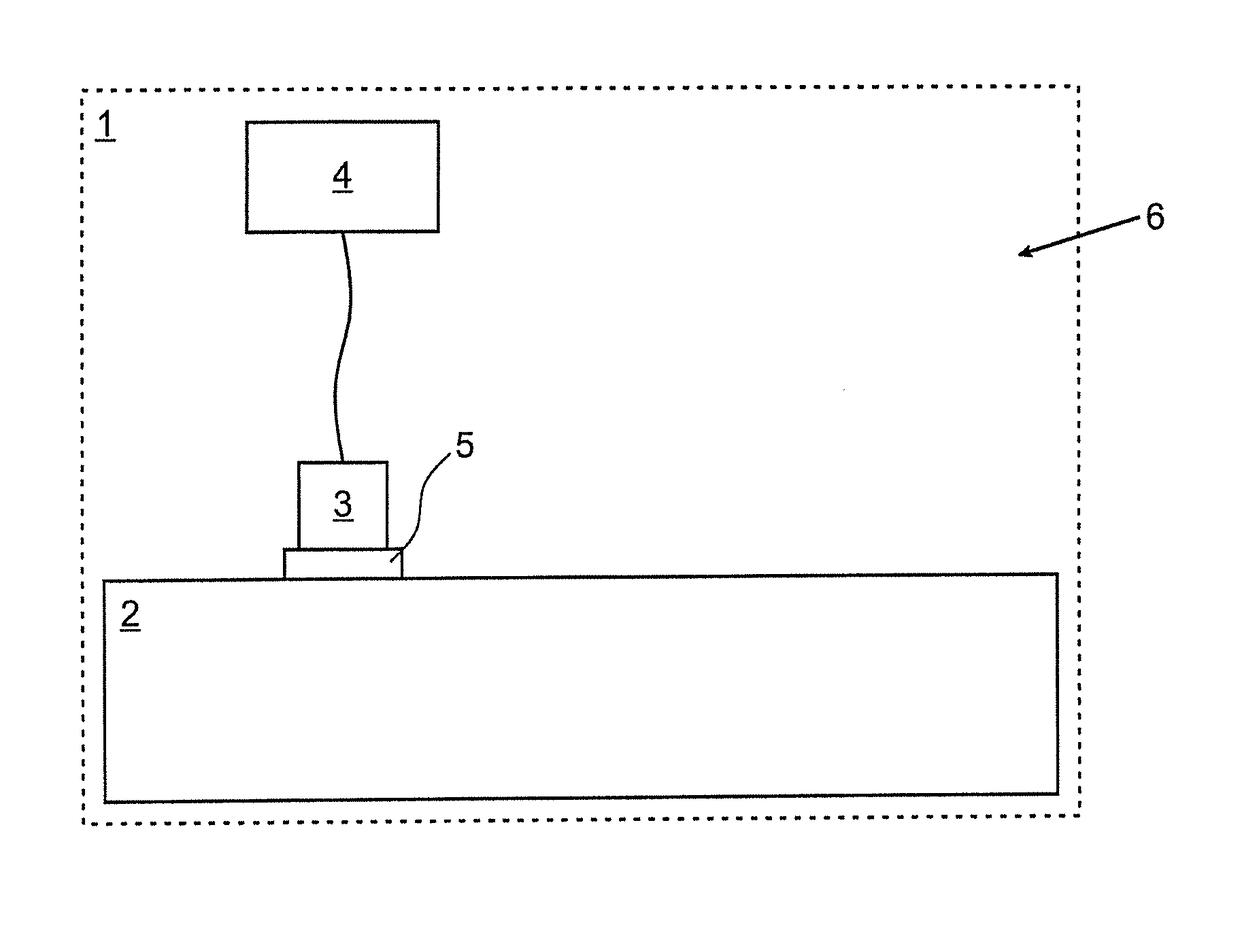
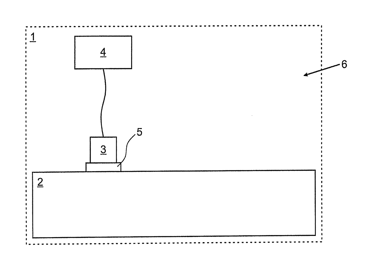
[0030]The Coriolis mass flowmeter 1 shown schematically in the FIGURE has a measuring tube 2, a sensor 3 and an evaluation unit 4.

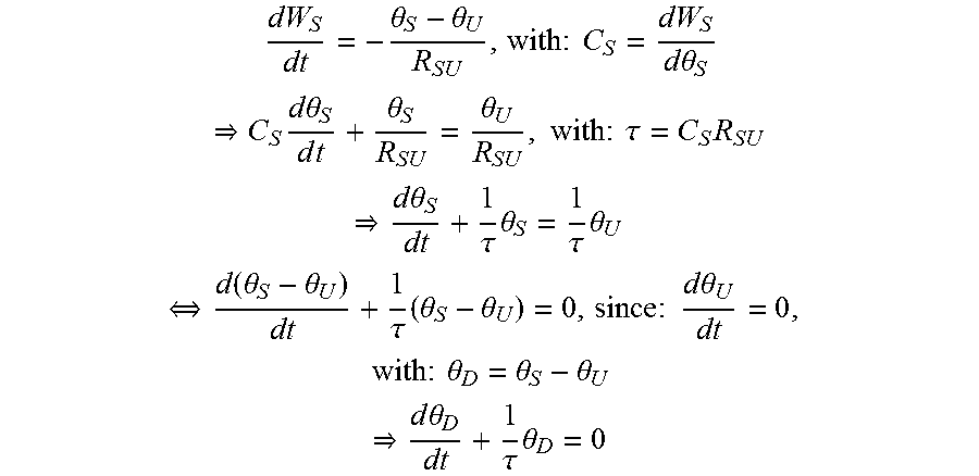
[0031]The sensor 3 is a temperature sensor and emits an electric sensor signal dependent on the temperature θS of the sensor 3. It is mechanically coupled to the rest of the Coriolis mass flowmeter 1 via a connection 5, wherein the temperature of the rest of the Coriolis mass flowmeter 1 is θU. The connection 5 is characterized by a thermal resistance RSU.

[0032]The evaluation unit 4 generates an excitation signal with the following characteristics. In the temporal course, there is a step from a first excitation value to a second excitation value. The first excitation value is thereby greater than the second excitation value. The excitation values are constant in terms of time before and after the step. The excitation signal is thus a step function. Since the first excitation signal is greater than the second excitation signal, then sensor 3 cools down aft...


PUM

PropertyMeasurementUnit
thermal resistanceaaaaaaaaaa
temperatureaaaaaaaaaa
time constantaaaaaaaaaa

Abstract

A method for operating a Coriolis mass flowmeter (1) having at least one measuring tube (2) and at least one sensor (3), wherein the sensor (3) emits an electric sensor signal depending on the temperature of the sensor (3), the sensor (3) is mechanically coupled to the rest of the Coriolis mass flowmeter (1) via a connection (5) and the connection (5) has a thermal resistance. To provide a method for operating a Coriolis mass flowmeter that makes recognition of a change in the connection possible an electric excitation signal is generated, the excitation signal is impressed in the sensor (3), the sensor signal influenced by the excitation signal is detected, a change between the detected sensor signal and a reference signal is determined and the change between the detected sensor signal and the reference signal is associated with a change in the thermal resistance.

Description

BACKGROUND OF THE INVENTION[0001]Field of the Invention[0002]The invention relates to a method for operating a Coriolis mass flowmeter having at least one measuring tube and at least one sensor, wherein the sensor emits an electric sensor signal depending on the temperature of the sensor, the sensor is mechanically coupled to the rest of the Coriolis mass flowmeter via a connection and the connection has a thermal resistance.[0003]Description of Related Art[0004]Furthermore, the invention relates to a Coriolis mass flowmeter having at least one measuring tube, at least one sensor and an evaluation unit, wherein the sensor emits an electric sensor signal depending on the temperature of the sensor, the sensor is mechanically coupled to the rest of the Coriolis mass flowmeter via a connection, and the connection has a thermal resistance.[0005]The functional principle of the Coriolis mass flowmeter is that the measuring tube having medium flowing through it is excited to oscillation, wh...

Claims


Application Information

Patent Timeline
Patent Type & Authority Patents(United States)
IPC IPC(8): G01F1/84G01K7/16G01F25/00
CPCG01F1/8431G01F1/845G01F1/8436G01K7/16G01F25/0007G01F1/8463G01F1/8409G01F1/84G01F25/10
Inventor KOLAHI, KOUROSHSTORM, RALF
Owner KROHNE MESSTECHNICK GMBH & CO KG
Learn More