Absorption refrigeration cycles using a LGWP refrigerant

a technology of absorption refrigeration and refrigerant, applied in the direction of refrigeration components, energy input, light and heating equipment, etc., can solve the problems of increasing and achieve the effect of reducing the cost of such systems

Active Publication Date: 2018-06-12
HONEYWELL INT INC
View PDF23 Cites 20 Cited by
  • Summary
  • Abstract
  • Description
  • Claims
  • Application Information

AI Technical Summary

Benefits of technology

[0025]The solution comprising the refrigerant and solvent is pumped against a means of resistance to increase the pressure of the solution. Pumping the liquid solution to a high operating pressure typically requires significantly less energy compared to compressing a vapor refrigerant using a compressor. In addition to expending less energy, pumps are typically less costly to install and maintain compared to compressors. This energy and cost savings is a distinct advantage of the present invention over conventional compression-type refrigeration systems.
[0026]The solution is also heated, preferably after being pressurized. Heating is preferably accomplished using a heat exchanger, such as shell-and-tube heat exchangers and plate heat exchangers or a distillation column. In a preferred embodiment, heating the solution involves a waste-heat recovery unit (WHRU) (i.e., a heat exchanger that recovers heat from a hot gas or liquid stream, such an exhaust gas from a gas turbine, heat generated in a solar collector or waste gas from a power plant or refinery). The WHRU working medium is preferably water—either pure or with triethylene glycol (TEG), thermal oil or other mediums conducive to heat transfer. In other embodiments, heating the solution involves the use of geothermal, solar derived heat or direct heating from combustion of a fuel such a propane.
[0027]After the solution is heated and pressurized, it is subjected to a thermodynamic separation process to produce a vapor refrigerant fraction and a liquid solvent fraction. Examples of such thermodynamic separation processes include column distillation and flashing. Since the two fractions are in different phases, they can be separated easily.
[0028]Preferably, the liquid solvent phase is recirculated back to the mixer, while the vapor phase comprising the refrigerant is transferred to a condenser where at least a portion, and preferably substantially all, of the refrigerant is converted from its vapor phase to a liquid phase.
[0029]The types of condenser useful in the invention are not particularly limited provided that they are suitable for condensing a hydrofluoroolefin or hydrochlorofluoroolefin refrigerant. Examples of condensers include horizontal or vertical in-shell condensers and horizontal or vertical in-tube condensers.
[0030]The liquid phase refrigerant is preferably passed through an expansion valve to lower the pressure of the refrigerant and, correspondingly, cool the refrigerant. The cooled, throttled refrigerant can be in a liquid-phase, vapor-phase, or a mixed-phase.

Problems solved by technology

Due to the toxicity and flammability of ammonia and the corrosive nature of lithium bromide, such systems are typically only used in industrial settings.
Another problem with such conventional systems is that the evaporator and the absorber are typically operated below atmospheric pressure which increases the cost of such systems because the equipment must be specially designed to work safely at low pressures.

Method used


Image

  • Absorption refrigeration cycles using a LGWP refrigerant
  • Absorption refrigeration cycles using a LGWP refrigerant
  • Absorption refrigeration cycles using a LGWP refrigerant

Examples


example 1

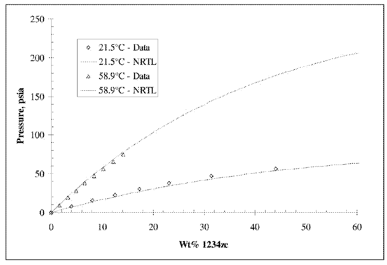
[0035]The solubility of trans-1,3,3,3-tetrafluoropropene (1234ze(E)) in Ford Motor craft oil (a PAG refrigerant compressor oil meeting Ford specification No. WSH-M1C231-B) was measured by means of a micro-balance. The solubility that was measured along with the correlation of the data using the Non-Random Two Liquid (“NRTL”) activity coefficient model (Renon H., Prausnitz J. M., “Local Compositions in Thermodynamic Excess Functions for Liquid Mixtures,” AIChE J., 14(1), S. 135-144, 1968)) is shown in FIG. 1. From these data it is seen that the Ford Motor Craft oil has nearly negligible vapor pressure and that the NRTL model can accurately represent the data.

example 2

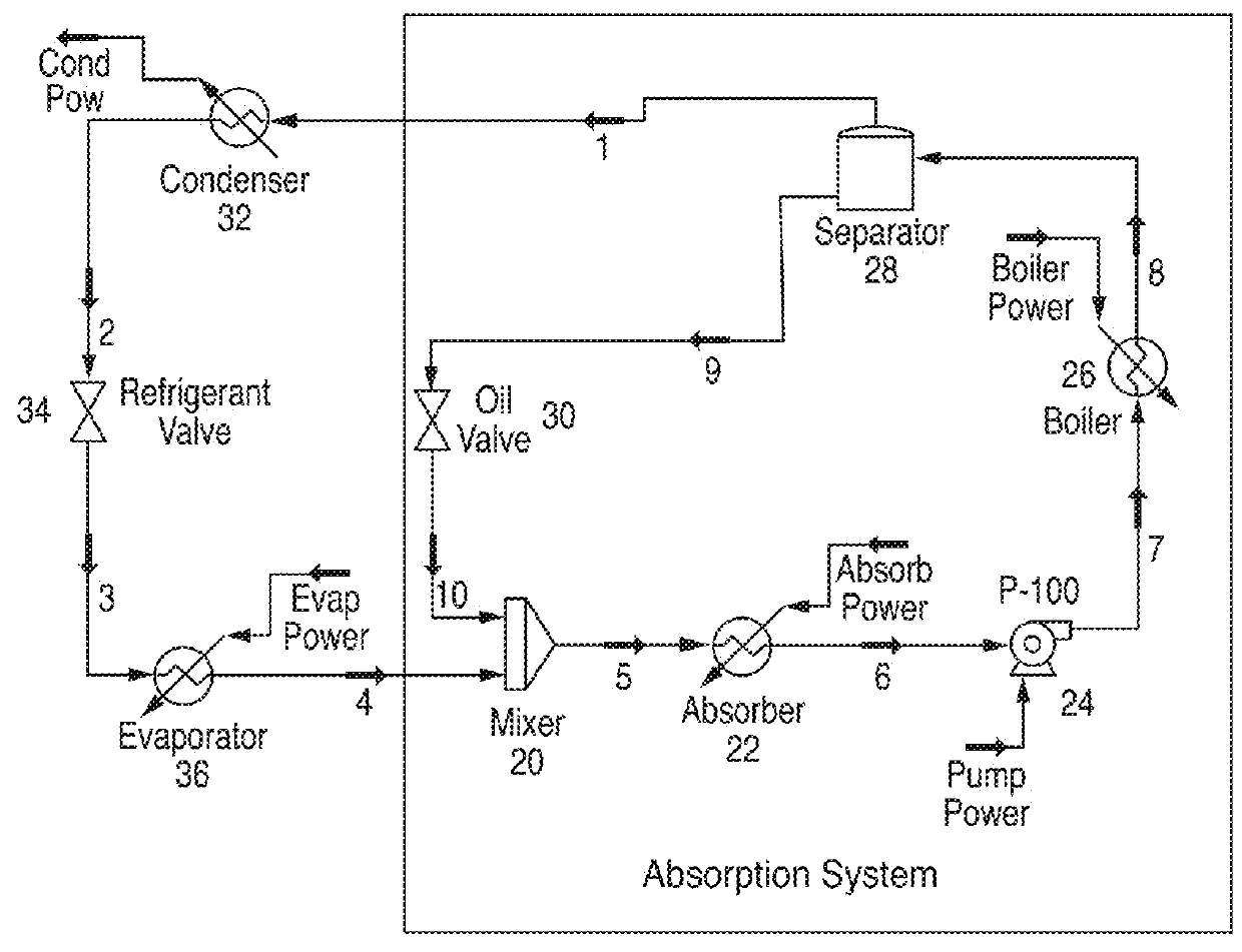
[0036]The data from examples 1 was used to develop a single effect absorption cycle. A representative schematic of a single effect absorption system of this invention is illustrated in FIG. 2.

[0037]In FIG. 2, a Ford Motorcraft polypropylene glycol dimethyl ether-based oil from line 10 is mixed with a liquid 1234ze(Z) refrigerant from line 4 in a closed mixer 20 (which can be a simple “T” joint connecting lines 4 and 10 to line 5). The mixture in passed though line 5 to an absorber 22 where the gaseous 1234ze(Z) dissolves into the oil. The liquid mixture is passed though line 6 to pump 24 that pressurizes the mixture and passes the mixture through line 7 to heat exchanger / boiler 26. In boiler 26, heat is exchanged with the mixture. The source of that heat can be waste heat from an industrial operation (e.g., power generation) external to the heat exchanger. The temperature of the mixture is raised to a temperature where the 1234ze(Z) refrigerant can separate from the oil. The heated ...

example 3

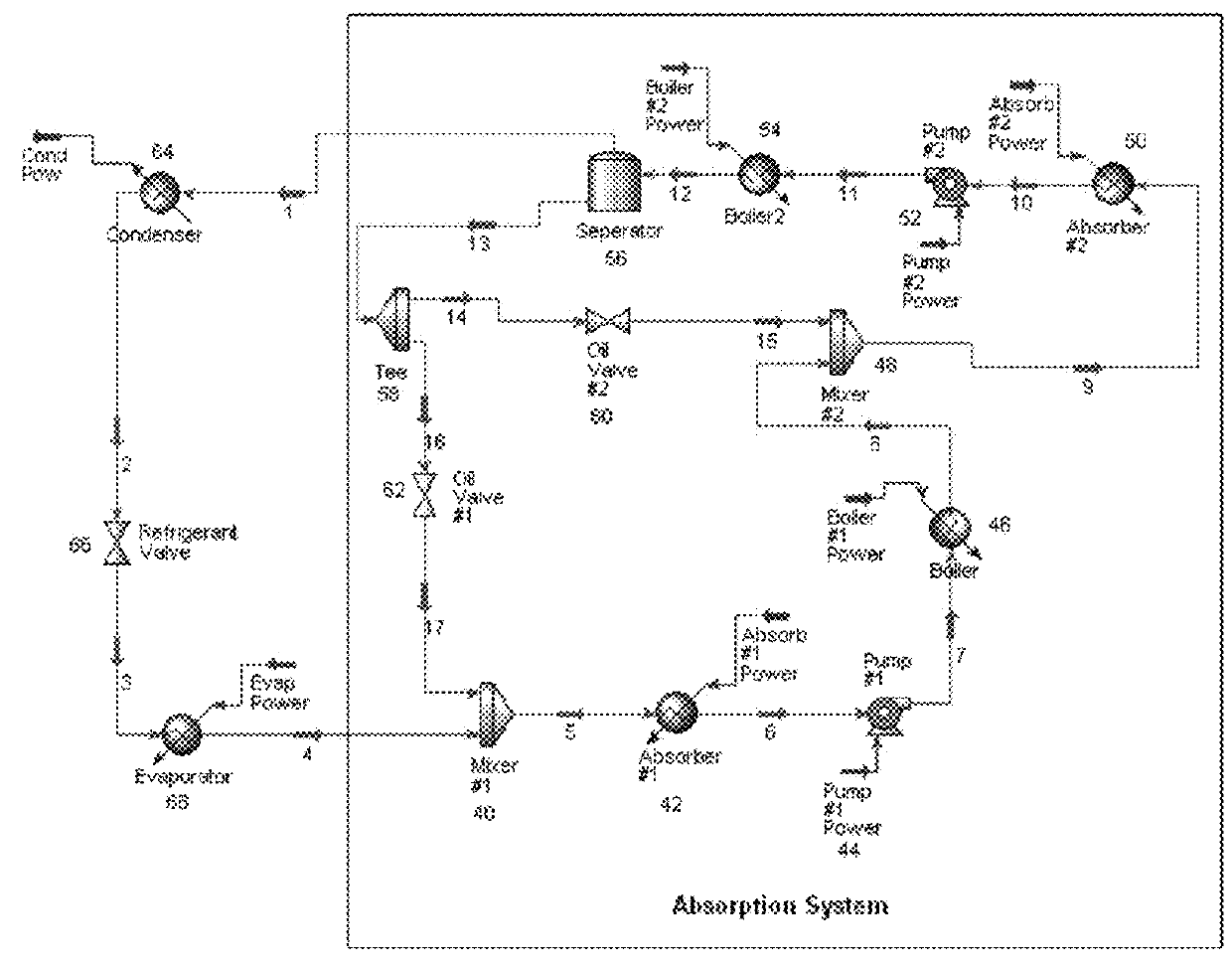
[0046]A representative schematic of a double effect absorption is illustrated in FIG. 3.

[0047]In FIG. 3, a Ford Motorcraft polypropylene glycol dimethyl ether-based oil from line 17 is mixed with a liquid 1234ze(Z) refrigerant from line 4 in a closed mixer 40. The mixture is passed though line 5 to a first absorber 42 where the gaseous 1234ze(Z) dissolves into the oil. The mixture is passed though line 6 to first pump 44 that pressurizes the mixture and passes the mixture through line 7 to first heat exchanger / boiler 46. In boiler 46, heat is exchanged with the mixture. The source of that heat can be waste heat from an industrial operation (e.g., power generation) external to heat exchanger 46. The temperature of the mixture is raised. The heated mixture is removed through line 8 from heat exchanger 46 and introduced to a second mixer 48 where it is mixed with oil from line 15. The mixture from mixer 48 is taken through line 9 and introduced to second absorber 50 to ensure that all ...


PUM

PropertyMeasurementUnit
temperatureaaaaaaaaaa

Abstract

An absorptive refrigeration method that employs a refrigerant comprising one or more hydrofluoroolefin or hydrochlorofluoroolefin refrigerants, and an oil selected from the group consisting of a polyalkyene glycol oil, a poly alpha olefin oil, a mineral oil and a polyolester oil.

Description

BACKGROUND OF THE INVENTION[0001]Field of Invention[0002]This invention relates to economical absorption refrigeration systems that employ refrigerants with low global warming potential (GWP) and low ozone depletion potential (ODP).[0003]Description of Prior Art[0004]Absorption refrigeration is a more economical alternative to compression refrigeration when a source of waste or other low-cost heat (e.g. solar heating) is available. Both absorption refrigerators and vapor compression refrigerators use a refrigerant with a very low boiling point. In both types, when this refrigerant evaporates or boils, it takes some heat away with it, providing the cooling effect. However, absorption refrigeration and vapor compression refrigeration differ in the way the refrigerant is changed from a gas back into a liquid so that the cycle can repeat. A vapor compression refrigerator uses an electrically-powered compressor to increase the pressure on the gas, and then condenses the hot high pressure...

Claims


Application Information

Patent Timeline
Patent Type & Authority Patents(United States)
IPC IPC(8): F25B15/02C09K5/04F25B15/00
CPCC09K5/047F25B15/008F25B15/02Y02P20/124Y02B30/62Y02P20/10Y02A30/27F25B1/00F25B15/00F25B27/00F25B43/00
Inventor HULSE, RYAN J.SINGH, RAJIV RATNA
Owner HONEYWELL INT INC
Why Eureka
Try Eureka