Sliding bearing arrangement for a wind turbine

a technology for sliding bearings and wind turbines, which is applied in the direction of sliding contact bearings, machines/engines, and final product manufacture, etc., can solve the problems of affecting the service life of the sliding bearing, etc., so as to achieve easy disassembly of the mechanical structure of the sliding bearing arrangement, easy exchange, and easy disassembly and assembly

Active Publication Date: 2018-06-12
SIEMENS GAMESA RENEWABLE ENERGY AS
View PDF17 Cites 19 Cited by
  • Summary
  • Abstract
  • Description
  • Claims
  • Application Information

AI Technical Summary

Benefits of technology

[0011]An aspect relates to an improved bearing arrangement, that provides access to exchange bearing pads while at the same time retaining the stability of the structure.

Problems solved by technology

The forces acting in the sliding bearing under operation lead to wear at the sliding surface.
This shows the disadvantage the openings, or parts that can be removed, weaken the bearing or the support structure.
This leads to additional fatigue of the bearing of the structure.

Method used


Image

  • Sliding bearing arrangement for a wind turbine
  • Sliding bearing arrangement for a wind turbine
  • Sliding bearing arrangement for a wind turbine

Examples


Embodiment Construction

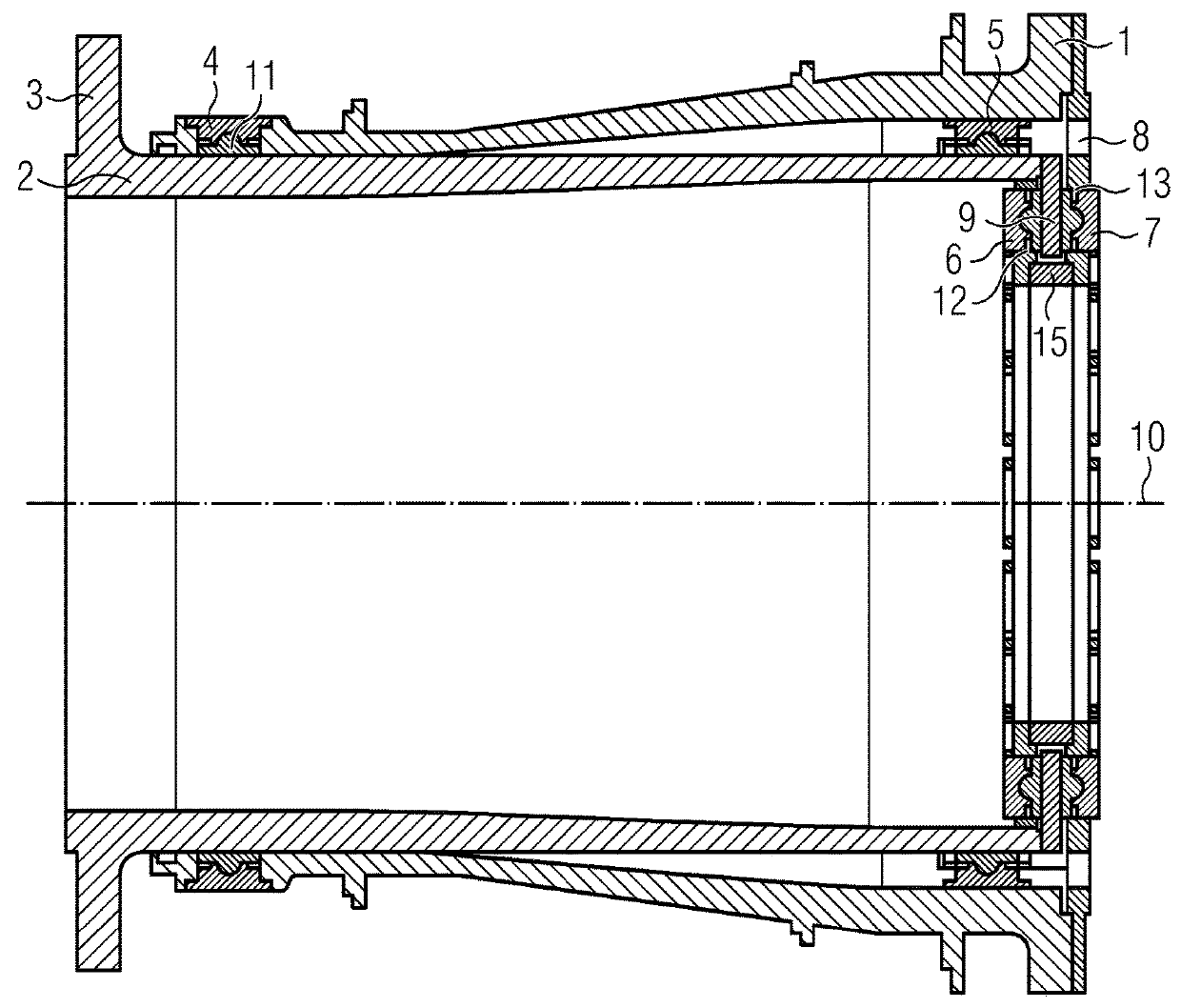
[0086]FIG. 1 shows a sliding bearing arrangement; the sliding arrangement can be used for a wind turbine.

[0087]The sliding bearing arrangement comprises a stationary shaft 1 and a rotatable shaft 2, that are arranged coaxially within each other and rotatable in respect to each other around an axis of rotation 10.

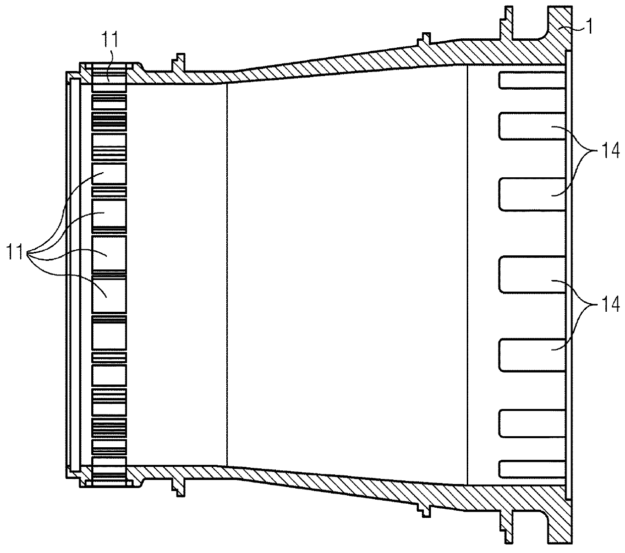
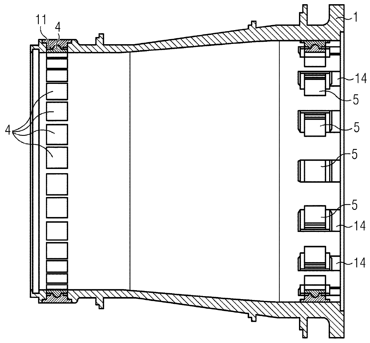
[0088]The arrangement comprises two radial bearings 4, 5 that support the rotatable shaft 2 in respect to the stationary shaft 1 in radial direction. The radial bearings 4, 5 are sliding bearings.

[0089]The stationary shaft 1 comprises a collar that is arranged perpendicular to the axis of rotation 10. The first radial sliding bearing 5 is arranged between the rotatable shaft 2 and the stationary shaft 1.

[0090]The collar that is attached to the stationary shaft 1 comprises an opening 8 that allows an exchange of the bearing pad of the first radial sliding bearing 5.

[0091]The collar that is connected to the stationary shaft 1 comprises a sliding bearing 7 that supports the rot...


PUM


Abstract

A sliding bearing arrangement for a wind turbine and a method to service the bearing is provided. A sliding bearing arrangement of a wind turbine includes a first shaft and a second shaft, whereby a first radial sliding bearing is arranged between the shafts. The first radial sliding bearing includes bearing pads. The first shaft includes a collar, whereby the collar is arranged mainly perpendicular to the axis of rotation, and radially overlaps at least a part of a radial surface of the second shaft. The collar includes an opening to exchange the bearing pads of the first radial sliding bearing of the bearing arrangement.

Description

CROSS-REFERENCE TO RELATED APPLICATIONS[0001]This application claims priority to European application No. EP16160125.7, having a filing date of Mar. 14, 2016, the entire contents of which are hereby incorporated by reference.FIELD OF TECHNOLOGY[0002]The following relates to a sliding bearing arrangement for a wind turbine and a method to service the bearing.BACKGROUND[0003]A wind turbine comprises one or more rotor blades. The rotor blades are connected to a hub. The rotor blades and the hub form the rotor of a wind turbine. The wind interacts with the rotor and causes a rotation of the rotor. The rotation of the rotor is transferred to an electrical generator. The rotational energy of the rotor is there transferred into electrical energy.[0004]The rotation of the rotor is often transferred over a shaft. The rotor, the shaft and the rotor of the generator are rotatable in respect to the stationary part of the wind turbine. The hub, and in cases the shaft, need to be connected to the...

Claims


Application Information

Patent Timeline
Patent Type & Authority Patents(United States)
IPC IPC(8): F16C17/10F16C17/26F16C43/02F03D80/70F03D80/50F16C17/04F16C17/02
CPCF03D80/50F03D80/70F16C17/10F16C17/26F16C43/02F05B2230/80Y02P70/523F05B2240/53F05B2240/54F16C17/02F16C17/04F16C2360/31Y02E10/72F05B2240/52F16C2300/14F16C2380/26Y02P70/50F16C33/26
Inventor STIESDAL, HENRIK
Owner SIEMENS GAMESA RENEWABLE ENERGY AS
Why Eureka
Try Eureka