Self test device and method for wireless sensor reader

a self-testing and wireless sensor technology, applied in the field of systems, can solve the problems of not allowing a separate reference reading, impractical to perform an accuracy check on the deployed sensor, impractical to conduct factory testing and calibration to determine or correct the accuracy of the system, etc., and achieve the effect of eliminating the variation in the self-test outcom

Active Publication Date: 2018-06-12
ENDOTRONIX
View PDF240 Cites 10 Cited by
  • Summary
  • Abstract
  • Description
  • Claims
  • Application Information

AI Technical Summary

Benefits of technology

[0024]In another embodiment, the self-test device may be configured to test the accuracy and functionality of the reader device. The self-test device may be configured to receive inputs from the reader device and provide sensor-like outputs. The sensor-like outputs of the self-test device may be predetermined and based on the input from the reader device. The reader device may be configured to perform a self-test by transmitting inputs to the self-test device, receiving outputs form the self-test device, and evaluating those outputs against predetermined values. The reader device may perform this evaluation on its own processor, or may relay its readings to another processor for analysis. The reader device may use the evaluated results to assess reader device health, flag potential problems, and initiate remedial action. The self-test device is configured to engage the reader device such that the known signal is provided from a known location related to an antenna or receiver of the reader device, to eliminate variation in self-test outcome due to random changes in spatial positioning. The test device may also be built into a docking station having a display wherein the docking station may be configured to charge the reader device.

Problems solved by technology

Known wireless sensor systems place a sensor in a remote location, where it is impractical to perform an accuracy check on the deployed sensor due to the environment in which the sensor is placed.
Many environments do not allow for a separate reference reading of the parameter being sensed due to the remote location's environmental or spatial constraints.
However, these reader and sensor systems may be field-deployed such that it may be impractical to conduct factory testing and calibration to determine or correct the accuracy of the system.
It may also be impractical or cost prohibitive to send a service technician to the field to check system accuracy.
This deformation leads to a deflection of the plate and hence a change in the capacitance value of the system.

Method used


Image

  • Self test device and method for wireless sensor reader
  • Self test device and method for wireless sensor reader
  • Self test device and method for wireless sensor reader

Examples


Embodiment Construction

[0043]Reference will now be made in detail to exemplary embodiments of the present invention, examples of which are illustrated in the accompanying drawings. It is to be understood that other embodiments may be utilized and structural and functional changes may be made without departing from the respective scope of the present invention.

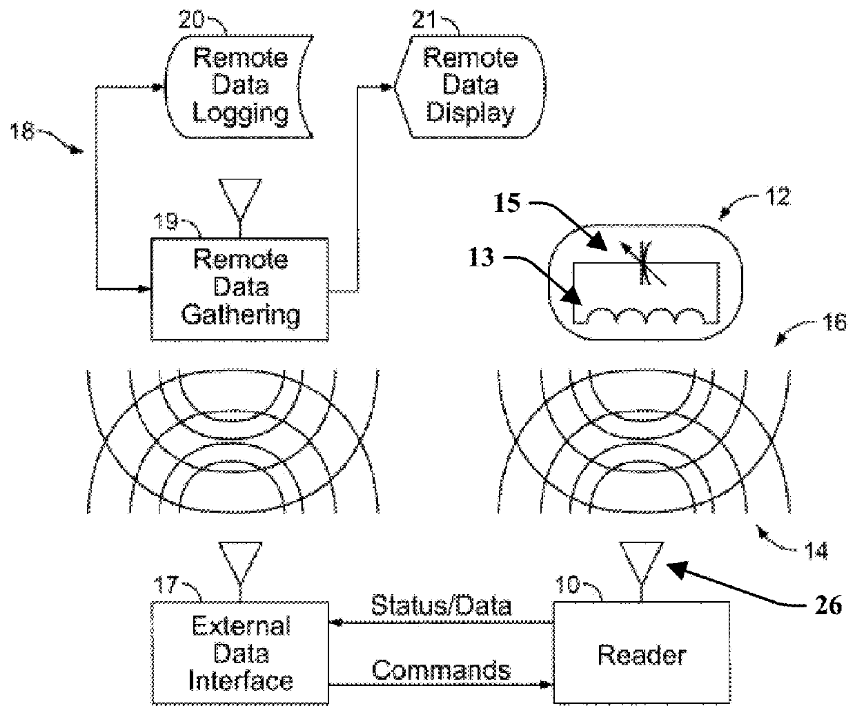
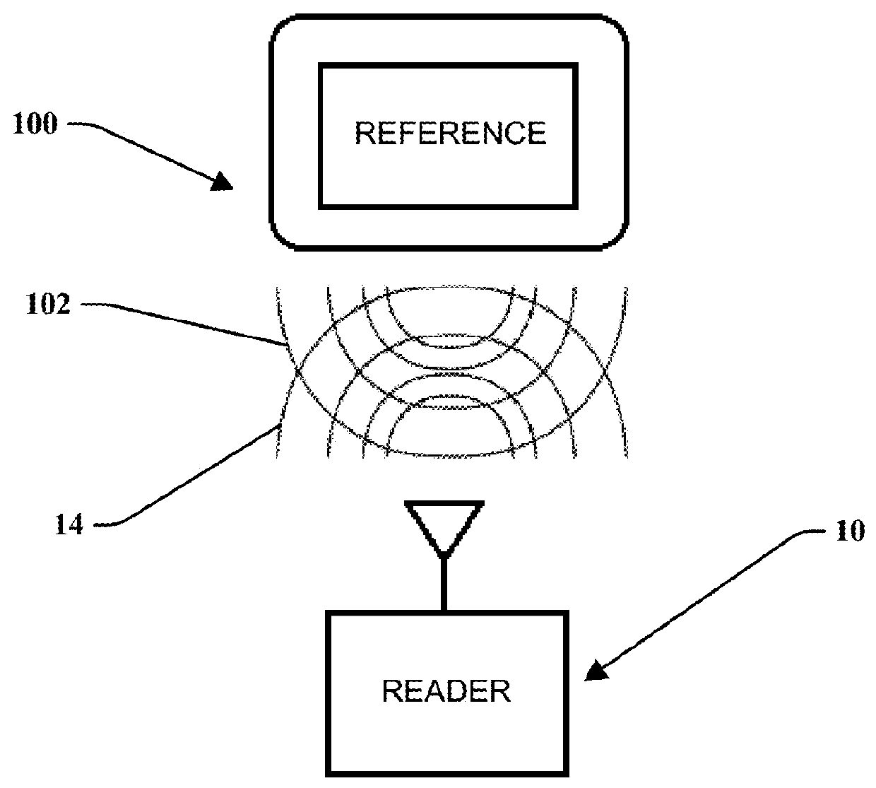
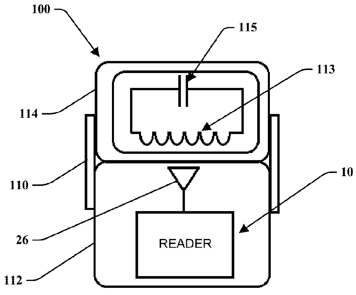
[0044]An apparatus and method for self-testing a wireless reader device is disclosed. As illustrated by FIG. 2, a self-test device comprising a sensor emulator 100 may be configured to wirelessly communicate reference data 102 with a reader device 10 that is configured to remotely and wirelessly communicate with a sensor 12, shown in FIG. 1. The self-test device 100 may be configured to behave in a manner that is electrically similar to the behavior of the wireless sensor 12, including producing a wireless signal that is electrically similar to that of wireless sensor 12, or receiving power or data transmissions from the reader in a manner similar to...


PUM


Abstract

Disclosed is a self-test device and method for assessing the functional performance of a reader device that is configured to interface with a wireless sensor. The self-test device may be configured to analyze the accuracy of a signal transmitted from the reader device or the accuracy of a signal received by the reader device. In one embodiment, the reader device may be configured to engage the self-test device to allow the reader to transmit a signal, such as a short pulse of energy or a short burst of radio frequency energy to cause the self-test device to output a resonant signal. The self-test device may receive the transmit signal from the reader and evaluate it against predetermined values. The evaluated signals may be used to assess the accuracy of the transmit signal of the reader device to identify potential calibration issues and initiate remedial action by an automated system or human intervention if needed. The self-test device may be built into a docking station where the reader is placed when not in use.

Description

TECHNICAL FIELD[0001]This invention relates generally to a system for testing a device configured for reading wireless sensors, and more particularly to a system and method for testing the device for functionality and accuracy.BACKGROUND[0002]Known wireless sensor systems place a sensor in a remote location, where it is impractical to perform an accuracy check on the deployed sensor due to the environment in which the sensor is placed. Many environments do not allow for a separate reference reading of the parameter being sensed due to the remote location's environmental or spatial constraints. In one example, the remote location is a body. Wireless sensor systems may generally include a reader unit or device that may have a configuration where it is placed in a use condition for taking readings from the sensor and in a resting condition in which it is not communicating with the sensor. For example, a reader unit may be handheld or battery operated and be adapted for use a few minute...

Claims


Application Information

Patent Timeline
Patent Type & Authority Patents(United States)
IPC IPC(8): G06K7/00H04Q9/00
CPCG06K7/0095H04Q9/00H04Q2209/88H04Q2209/86H04Q2209/823
Inventor SUNDARAM, BALAMURUGANNAGY, MICHAELNIELSEN, DOUGLASSUNDARAM, SURESH
Owner ENDOTRONIX
Why Eureka
Try Eureka