Failure mode protection for electromechanical battery

a technology of electromechanical batteries and failure modes, applied in the direction of magnetic bearings, magnetic circuit rotating parts, magnetic circuit shapes/forms/construction, etc., to achieve the effect of slowing down the rotation of the rotor

Inactive Publication Date: 2018-06-12
LAWSON II ROBERT W
View PDF14 Cites 1 Cited by
  • Summary
  • Abstract
  • Description
  • Claims
  • Application Information

AI Technical Summary

Benefits of technology

[0007]The electromechanical battery of the disclosure is able to slow down the rotation of the rotor within the electromechanical battery by a second material composition or boric acid coming into contact with the rotary member. The rotation of the rotor is able to be stopped by the rotary member converting into a third material composition or a polymeric silicone. The third material composition or the polymeric silicone is able to absorb energy, such as kinetic energy, stored within the spinning rotary member.

Problems solved by technology

One problem with high rotational speed spinning rotors being used to store energy relates to failure modes, where the electromechanical battery is subject to being impacted during a collision, or where a spinning rotor fails for some other reason.
The high rotation speed of the rotor stores a large amount of stored energy and consequently requires safeguards for disposal or dissipation of the stored residual energy.

Method used


Image

  • Failure mode protection for electromechanical battery
  • Failure mode protection for electromechanical battery
  • Failure mode protection for electromechanical battery

Examples


Embodiment Construction

[0016]The explanations and illustrations presented herein are intended to acquaint others skilled in the art with the invention, its principles, and its practical application. The specific embodiments of the present invention as set forth are not intended as being exhaustive or limiting of the invention. The scope of the invention should be determined with reference to the appended claims, along with the full scope of equivalents to which such claims are entitled. The disclosures of all articles and references, including patent applications and publications, are incorporated by reference for all purposes. Other combinations are also possible as will be gleaned from the following claims, which are also hereby incorporated by reference into this written description.

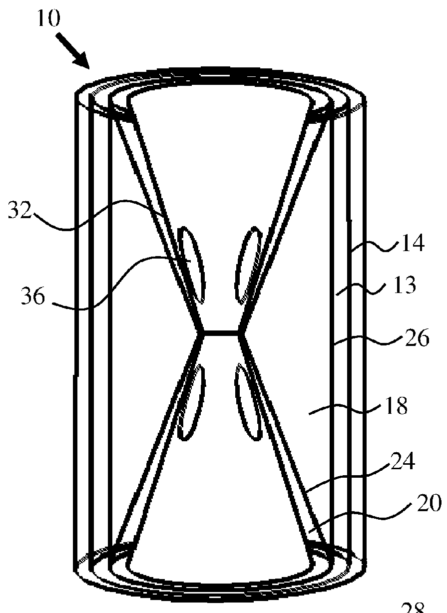
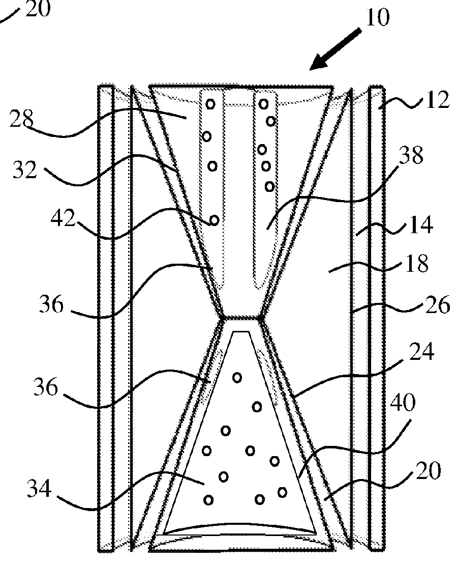
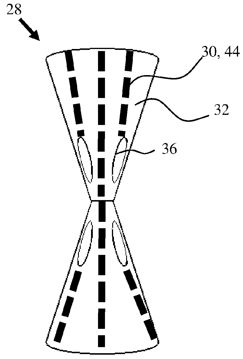
[0017]An electromechanical battery (EMB) can be suitable for the storage of energy, regulation of energy, transmission of energy, or the like. The electromechanical battery can function to store kinectric energy. The electr...


PUM


Abstract

An electromechanical battery can include a rotary member made at least in part of a first material composition. The rotary member having an interior surface defining an internal core cavity and at least one central chamber. A plurality of permanent magnets supported by the interior surface of the core cavity. A core member can be disposed within the core cavity. At least one levitating magnet can be supported by an exterior surface of the core member. The rotary member levitated with respect to the core member by the permanent magnets and levitating magnet. A second material composition can reside within at least one of the rotary member and the core member. The first member material composition converts through chemical reaction when exposed to the second material composition into a third material composition. The third material composition characterized by energy absorption resisting continued rotation of the rotary member.

Description

FIELD OF INVENTION[0001]The present invention relates generally to an electromechanical battery (EMB), and more particularly, to energy absorption for failure mode protection of an electromechanical battery.BACKGROUND[0002]Electromechanical batteries (EMB) have been considered as alternative energy storage systems in the automotive industry. Generally, an EMB, such as a flywheel has been used to store energy with the use of an electric motor. Traditional flywheel electromechanical batteries include an electric motor which spins a rotor at high rotational speeds to store energy and the energy is then discharged by driving an electric generator with the spinning flywheel when power is needed. The rotor can be rotated within a housing unit through a combination of electrical current and magnets. One problem with high rotational speed spinning rotors being used to store energy relates to failure modes, where the electromechanical battery is subject to being impacted during a collision, ...

Claims


Application Information

Patent Timeline
Patent Type & Authority Patents(United States)
IPC IPC(8): H02K7/102H02K7/02H02K1/27H02K5/04
CPCH02K7/102H02K7/025H02K5/04H02K1/278Y02E60/16F16C2361/55F16C32/0408H02K1/2753H02K1/2783
Inventor LAWSON, II, ROBERT W.
Owner LAWSON II ROBERT W
Why Eureka
Try Eureka