Automatic speed changer

Inactive Publication Date: 2005-10-13
AISIN AW CO LTD
View PDF7 Cites 0 Cited by
  • Summary
  • Abstract
  • Description
  • Claims
  • Application Information

AI Technical Summary

Benefits of technology

[0010] Accordingly, while providing an automatic transmission which is directly coupled in fifth speed forward, which provides at least five forward speeds and one reverse speed, the reduced speed rotation output means and the planetary gear unit can be located closer together, as compared to the case wherein a clutch is located between the reduced speed rotation output means and the planetary gear unit for example, and the transmitting element(s) for transmitting the reduced speed rotation can be made relatively short. Therefore, the automatic transmission can be made compact and lightweight, and further, because the inertia (inertial force) can be reduced, the controllability of the automatic transmission can be improved, and the occurrence of speed change shock can be reduced. Further, in the case that, for example, the reduced speed rotation output means has a clutch, three clutches are required, but compared to the case wherein three clutches are lo

Problems solved by technology

Further, the weight of such a unit would be heavier, and not only would a lightweight automatic transmission become impossible, but inertia (inertial force) would increase, thereby reducing the controllability of the automatic transmission and speed change shocks would become more likely to occur

Method used


Image

  • Automatic speed changer
  • Automatic speed changer
  • Automatic speed changer

Examples


first embodiment

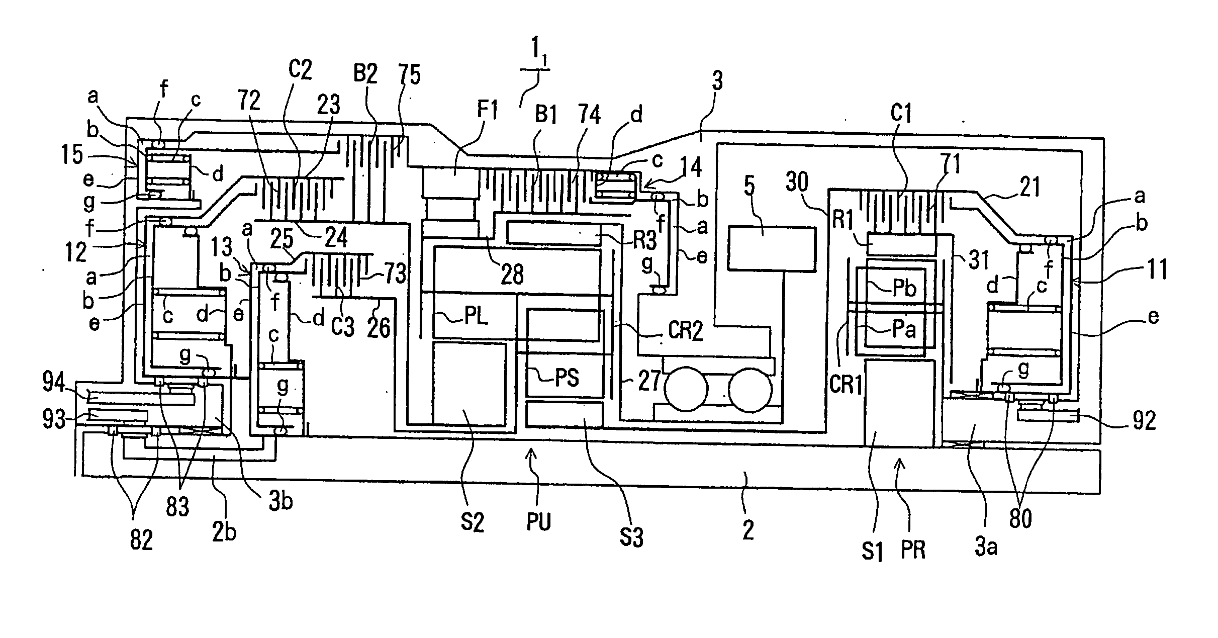
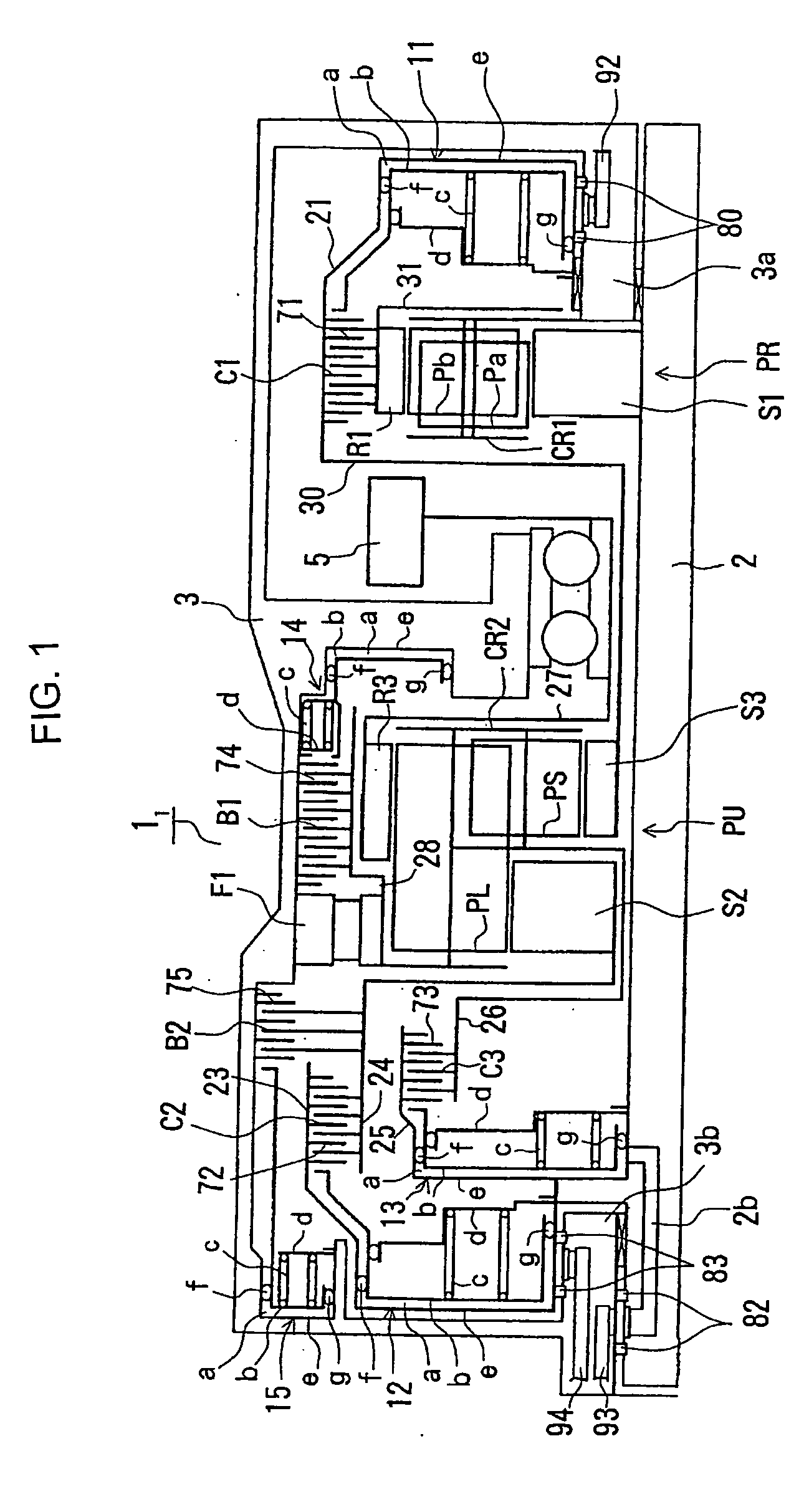
[0046] A first embodiment of the present invention will be described with reference to FIG. 1 through FIG. 3.

[0047] The automatic transmission 11 of the first embodiment of the present invention, as illustrated in FIG. 1, is particularly useful for a FF (front engine, front wheel drive) vehicle, and has a case comprising a housing for a torque converter, not illustrated, and a transmission case 3 housing automatic transmission 11, a counter shaft unit (drive wheel transmission mechanism), not illustrated, and a differential unit (drive wheel transmission mechanism).

[0048] The torque converter is located on an axis centered on an input shaft 2 of the automatic transmission device 11, which is on the same axis as the output shaft of the engine (not illustrated). Further, the counter shaft unit includes a counter shaft (not illustrated) on an axis that is parallel to the input shaft 2, and the above-mentioned differential unit has a lateral axle, not illustrated, on an axis that is p...

second embodiment

[0081] The second embodiment, which is a partial modification of the first embodiment, will be described with reference to FIG. 4. Components of the second embodiment which are the same as those of the first embodiment are denoted by the same reference numerals, and description thereof omitted, except for those components which are modified.

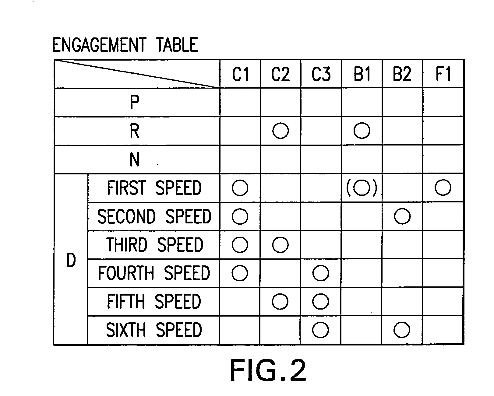
[0082] As FIG. 4 illustrates, the automatic transmission 12 of the second embodiment has the input side and output side reversed from that of the automatic transmission 11 of the first embodiment (see FIG. 1). Further, the operations of first speed forward through the sixth speed forward and the first speed reverse are similar (see FIG. 2 and FIG. 3).

[0083] Accordingly, similar to the first embodiment, in the automatic transmission 12 of the second embodiment, the second planetary gear unit PR and the clutch C1 are located on one axial side of the first planetary gear unit PU, and the clutch C2 and the clutch C3 are located on the other axial s...

third embodiment

[0089] The third embodiment, which is a partial modification of the first embodiment will now be described with reference to FIG. 5 through FIG. 7. Components of the third embodiment which are the same as those of the first embodiment are denoted by the same reference numerals, and description thereof omitted, except for components which are partially modified.

[0090] As FIG. 5 illustrates, the automatic transmission 13 of the third embodiment has a modified second planetary gear unit PR and modified clutch C1, and further, a modified oil line for supplying oil pressure to hydraulic servo 11 of the clutch C1, as compared to the automatic transmission 1, of the first embodiment (see FIG. 1).

[0091] Within the automatic transmission 13, the clutch C1 is located on the side of the second planetary gear unit PR opposite the planetary gear unit PU. The inner circumferential surface of the drum 21 of clutch C1 is splined to the friction plates 71 which are intermeshed with friction plates...


PUM


Abstract

A second planetary gear unit PR and a clutch C1 for outputting reduced speed rotation are located on one axial side of a first planetary gear unit PU, with an output unit located therebetween. A clutch C2 which connects/disconnects an input shaft 2 to/from a sun gear S2 of the planetary gear unit PU and a clutch C3 connects and disconnects the input shaft to/from a carrier CR2 of the planetary gear unit are on the other axial side of the first planetary gear unit PU. Compared with a transmission wherein a clutch C2 or clutch C3 is located between the second planetary gear unit PR and the planetary gear unit PU, the second planetary gear unit PR and the first planetary gear unit PU can be located closer together, and a member which transmits the reduced speed rotation can be made shorter. Further, compared to the case wherein, for example, the clutches C1, C2, C3 are located together on one axial side, oil supply to their servos is simplified.

Description

CROSS-REFERENCE TO RELATED APPLICATIONS [0001] This application is a National Phase Application (35 USC 371) of PCT / JP2003 / 017066 and claims priority of Japanese Application No. 2002-279860 filed Sep. 25, 2002.TECHNICAL FIELD [0002] The present invention relates to an automatic transmission mounted on a vehicle, and more specifically, it relates to the design of an automatic transmission wherein multiple speed levels are established by input of reduced speed rotation into one of the rotatable components of a planetary gear unit. BACKGROUND ART [0003] Generally, a vehicular automatic transmission comprises two linked planetary gear units, and planetary gearing for reducing speed of the rotation received from the input shaft (for example, see Japanese Unexamined Patent Application Publication No. 4-125345). Such a transmission achieves, for example, six forward speeds and one reverse speed, by input of reduced speed rotation from the planetary gearing via a clutch to, for example, one...

Claims


Application Information

Patent Timeline
IPC IPC(8): F16H3/66
CPCF16H3/663F16H3/666F16H2200/2023F16H2200/2007F16H2200/0052
Inventor KAYAMA, KAZUMICHISUGIURA, NOBUTADAYAMAGUCHI, SHUNDOSUGIMOTO, TATSUYAINAGAKI, TOMOCHIKA
Owner AISIN AW CO LTD
Why Eureka
Try Eureka