
Wind turbine system

a wind turbine and wind power technology, applied in the direction of magnetic circuit rotating parts, greenhouse gas reduction, shape/form/construction of magnetic circuits, etc., can solve the problems of complex system structure, lack of reliability and efficiency, and difficulty in extracting, discharging, and accounting for the generated electrical power, etc., to achieve the effect of slowing down the rotation of the dis

Active Publication Date: 2018-08-14
EQUIP WIND WILL
View PDF14 Cites 0 Cited by
  • Summary
  • Abstract
  • Description
  • Claims
  • Application Information

AI Technical Summary

Benefits of technology

The patent is for a brake assembly that uses magnets to hold a slot in place and slow down a disc's rotation. The processing unit identifies which slot is in the magnet's opening and sends a control signal to activate the magnet. This technology allows for precise control over braking and improved efficiency in braking systems.

Problems solved by technology

However, such systems are typically complex and bulky, lack reliability and efficiency, in addition to not being profitable in the long run.
It may also be difficult to extract, distribute, and account for the generated electrical power.

Method used


Image

  • Wind turbine system
  • Wind turbine system
  • Wind turbine system

Examples


Embodiment Construction

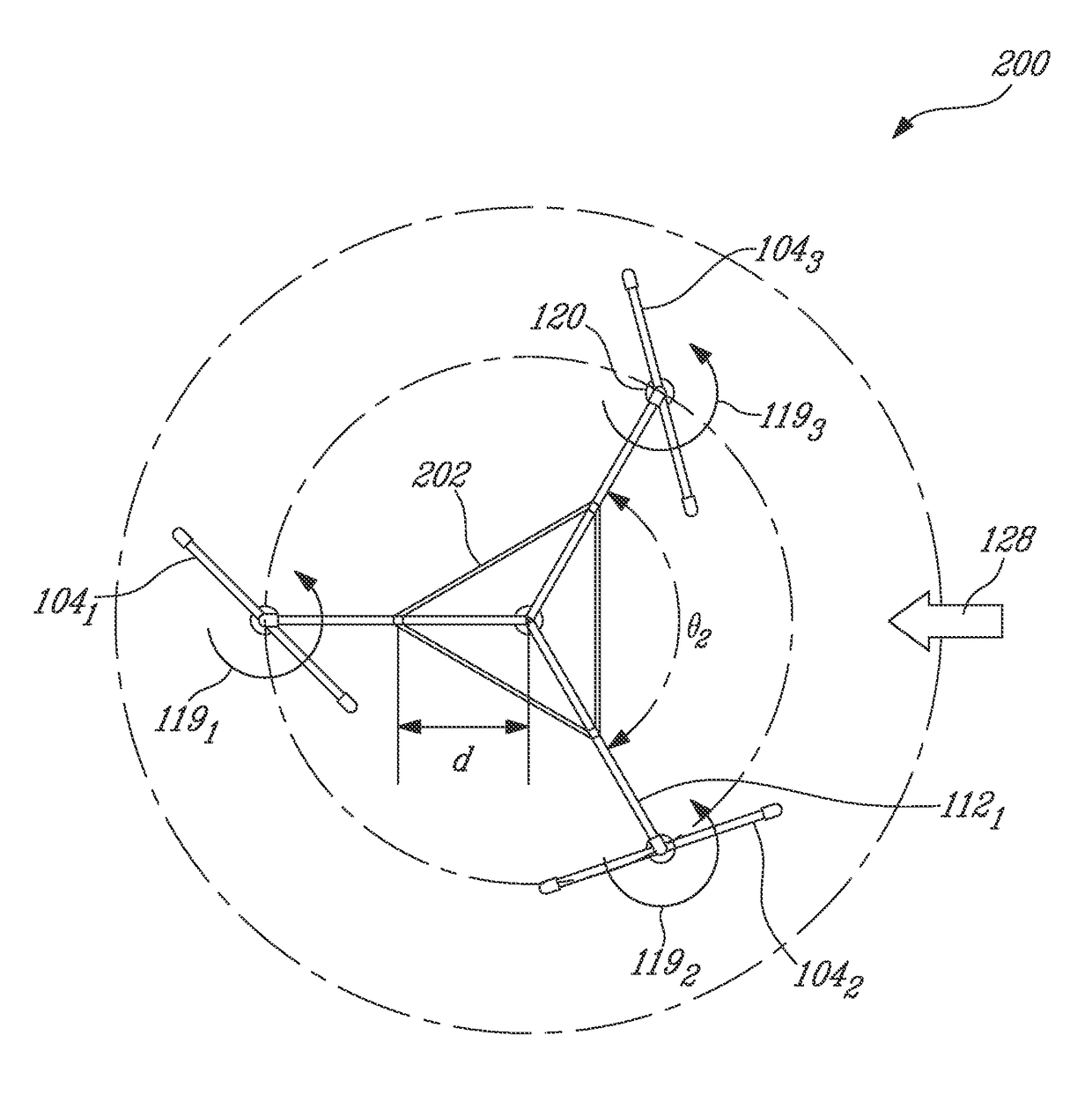
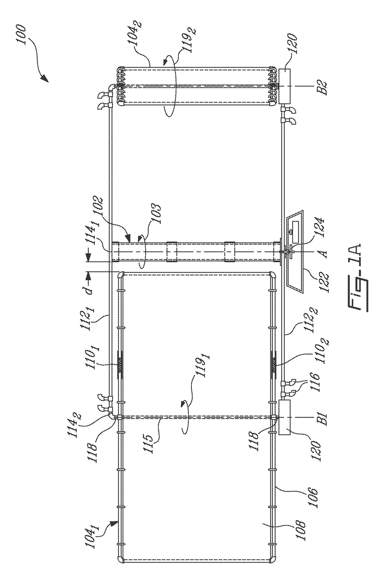
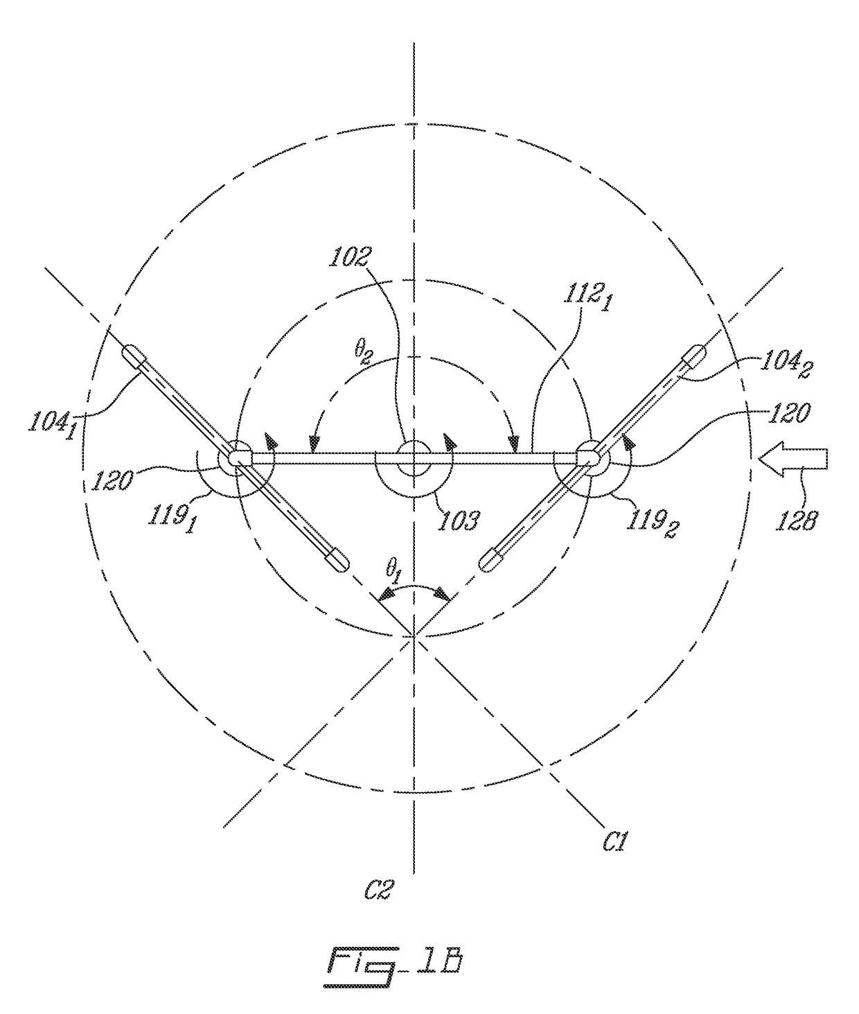
[0058]FIG. 1A illustrates an exemplary wind turbine system 100. The wind turbine system 100 is illustratively a vertical-axis wind turbine, that comprises a central pole 102, which has a longitudinal axis A and is adapted to rotate thereabout in the direction of arrow 103. Although the central pole 102 is illustrated as rotating in a counter-clockwise direction 103, it should be understood that bi-directional rotation of the central pole 102 may apply and that the central pole 102 may therefore also rotate in a clockwise direction. The wind turbine system 100 further comprises a plurality (two (2) in the illustrated embodiment) of blades as in 1041, 1042, each blade 1041 or 1042 comprising a frame 106 that supports a surface 108. The dimensions of the frame 106 are illustratively selected in accordance to the level of electrical power that is to be generated by the wind turbine system 100 at a given wind speed. In one embodiment, if it is desired to convert kinetic energy from wind ...


PUM


Abstract

A wind turbine system includes a current generator having a planar base member, a connection member secured at a geometrical center of the base member and configured to rotate about an axis transverse to a plane of the support member upon exertion of wind pressure on the wind turbine, a rotor assembly secured to the connection member for rotation about the axis, the rotor assembly spaced from the base member and including planar rotor members spaced from and parallel to one another; and a planar stator assembly secured to the base member and centered in a spacing between the rotor members, the stator assembly configured to generate a current upon rotation of the rotor assembly relative thereto. A control system supplies power from the generator to an electrical grid. A control system adjusts an angular position of the turbine blades. A wind sensor measures a differential wind pressure.

Description

CROSS REFERENCE TO RELATED APPLICATIONS[0001]The present patent application is a US National Stage of International Application No. PCT / CA2014 / 000081, filed on Jan. 27, 2014, which claims priority of U.S. provisional Application Ser. No. 61 / 757,107, filed on Jan. 26, 2013.TECHNICAL FIELD[0002]The present invention relates to the field of wind turbine systems.BACKGROUND OF THE ART[0003]Wind turbine systems are used to convert wind energy into electrical power. However, such systems are typically complex and bulky, lack reliability and efficiency, in addition to not being profitable in the long run. It may also be difficult to extract, distribute, and account for the generated electrical power.[0004]There is therefore a need for an improved wind turbine system.SUMMARY[0005]In accordance with a first broad aspect, there is provided a current generator for a wind turbine, the generator comprising a substantially planar base member; a connection member secured to the base member at a geo...

Claims


Application Information

Patent Timeline
Patent Type & Authority Patents(United States)
IPC IPC(8): F03D3/06F03D7/06F03D9/25F03D9/00H02K3/26H02K1/18H02K1/27H02K7/18H02K21/24G01P5/14
CPCF03D3/068F03D7/06G01P5/14H02K1/182H02K1/2793H02K3/26F03D9/25H02K21/24H02K7/183F05B2260/76F05B2260/902H02K2211/03H02K2213/09Y02E10/74Y02E10/728H02K1/2795F03D3/02F03D13/22F03D9/255
Inventor KISOVEC, JEAN-FRANCIS
Owner EQUIP WIND WILL
Learn More