Method and apparatus for driving surface discharge plasma display panel

a plasma display and surface discharge technology, applied in the direction of gas-filled discharge tubes, electric discharge tubes, instruments, etc., can solve the problems of deteriorating pdp contrast, destabilizing the operation of pdp or lowering display quality, etc., to prevent an unnecessary current flow

Inactive Publication Date: 2001-03-06
HITACHI PLASMA PATENT LICENSING
View PDF8 Cites 38 Cited by
  • Summary
  • Abstract
  • Description
  • Claims
  • Application Information

AI Technical Summary

Benefits of technology

An object of the present invention is to provide a method and an apparatus for driving a surface discharge plasma display panel with a wide range of voltages for causing address discharge, to improve the display quality of the panel. Further, another object of the present invention is to provide a method and an apparatus for driving a surface discharge plasma display panel that displays black with low luminance, to improve the display quality of the panel.
The first electrode may receive an output of an X-common driver, the second electrodes may receive outputs of Yi-drive circuits, and the third electrodes may receive outputs of Aj-drive circuits; and the Yi-drive circuits may be connected to a Y-common driver, the second electrodes may be driven by a positive pulse during a sustain discharge period, and the second electrodes may be driven by negative pulses during an address period. The Y-common driver may include a first switching unit for preventing an unnecessary current flow into the Yi-drive circuits caused by using the positive and negative pulses. The first switching unit may be controlled by a second switching unit which is used to apply the negative pulses to the second electrodes through the Yi-drive circuits.

Problems solved by technology

The fluctuations also change an optimum value of the potential, to destabilize the operation of the PDP or lower the display quality thereof.
However, the discharge produces light even when displaying black, and thus the contrast of PDP is deteriorated.

Method used


Image

  • Method and apparatus for driving surface discharge plasma display panel
  • Method and apparatus for driving surface discharge plasma display panel
  • Method and apparatus for driving surface discharge plasma display panel

Examples


first embodiment

As described above, the present invention carries out the write discharge in all cells in the selected line and then carries out the self-erase discharge to nearly completely neutralize the wall charges. Accordingly, the conditions of all cells in the selected line are equalized before display data are written in the selected line. This results in expanding the range of the potential Va, always carrying out stable address discharge with no regard to the distribution of charges before the write discharge or changes in temperature, preventing write errors, and improving the display quality of the PDP.

Further, unlike the prior art of FIG. 2, no discharge occurs between the sustain electrodes X and Ys in the cells to be turned OFF in the process (1-c), so that the number of light emitting discharge operations carried out in all cells in the selected line is two in the write cycle, which is 2 / 3 of the operations used in the prior art. Accordingly, the ratio of the maximum luminance and t...

second embodiment

As described above, the second embodiment carries out the total write discharge and then the self-erase discharge to nearly completely neutralize wall charges. Accordingly, the conditions of all cells in a selected line are equalized before display data are written in the selected line during the address period. This results in expanding the range of the potential Va, always carrying out stable address discharge with no regard to the distribution of charges before write discharge or changes in temperature, preventing write errors, and improving the display quality of the PDP. Further, the number of discharge emissions in the reset period in each sub-field is two, which is 2 / 3 of the emission in the prior art. Namely, the ratio of the maximum luminance to the minimum luminance for displaying black is increased by 3 / 2 of the prior art, to thereby improve the quality of displaying shades of gray.

third embodiment

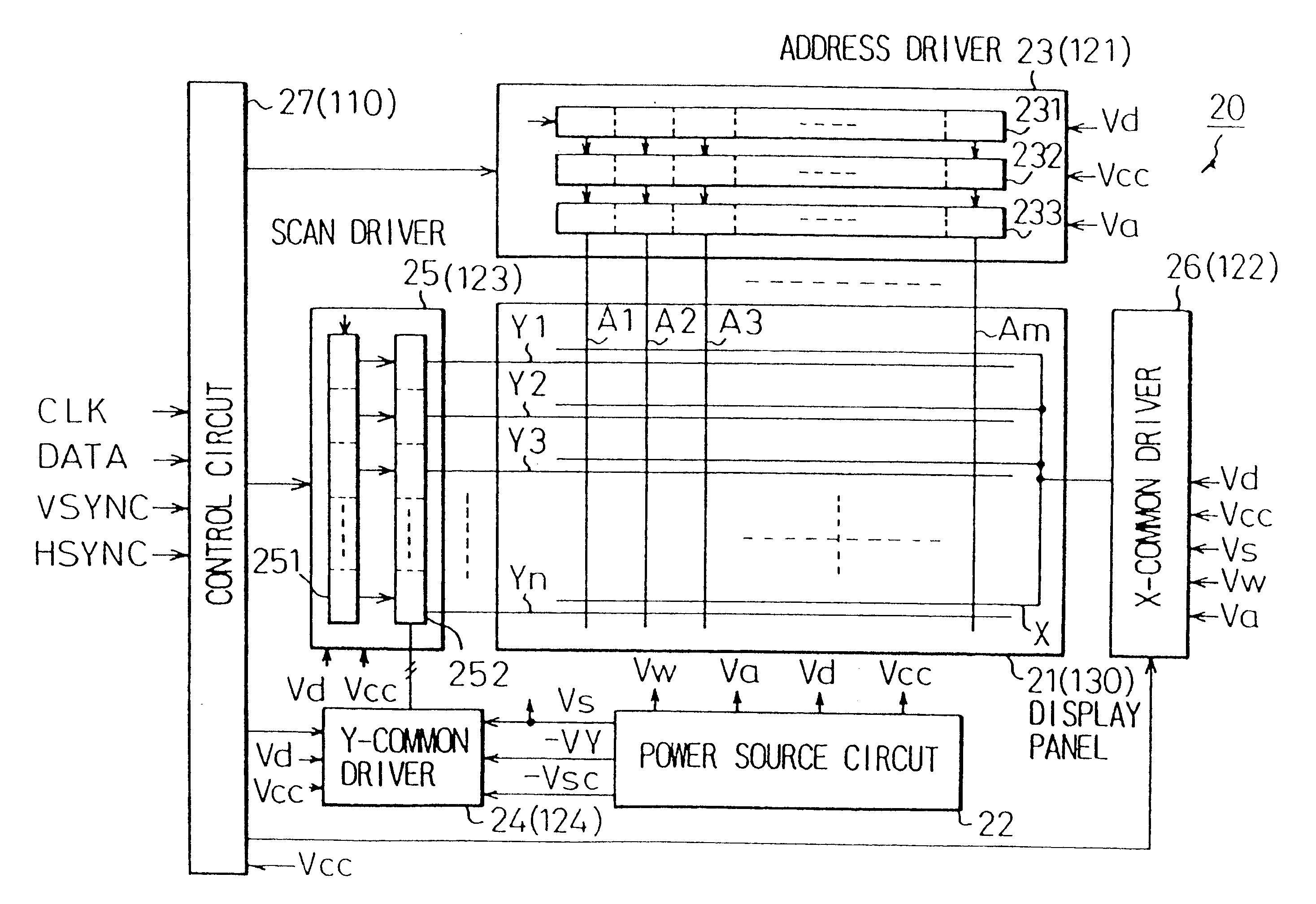
FIG. 10 shows a sub-field of voltage waveforms applied to the electrodes according to a PDP driving method based on the present invention. In FIG. 10, (i), (ii), (iii), (iv) and (v) are waveforms of address electrodes Aj, sustain electrodes X, sustain electrode Y1, sustain electrode Y2 and sustain electrode Yn, respectively.

By the way, a scan driver and an X-common driver (X driver) for carrying out sustain discharge and total write discharge consume larger power than other drivers, and are, therefore, large. On the other hand, a positive pulse generator is simpler and cheeper than the negative pulse generator. Therefore, the third embodiment of the present invention employs only positive pulses during the reset and sustain discharge periods.

(3-a) First, in the reset period, all electrodes are set to 0V, and a write pulse 222 of Vs+Vw is applied to the sustain electrodes X. At the same time, a pulse of Vaw is applied to the address electrodes A1 through Am. The reason why the potent...


PUM


Abstract

A method of driving a surface discharge plasma display panel has a reset step of applying a pulse of a first voltage to paired first and second electrodes, a write step of applying a pulse of a second voltage to second and third electrodes corresponding to cells to be turned ON, and a sustain discharge step of applying an AC pulse of a fourth voltage to the paired first and second electrodes. The pulse of the first voltage is so set that it is higher than a first discharge start voltage, a third voltage caused by the discharge is higher than the first discharge start voltage, and the first, second, and third electrodes have the same potential after the application of the pulse of the first voltage. Therefore, an address discharge of the surface discharge plasma display panel can be caused by a wide range of voltages, and display quality of the panel can be improved.

Description

BACKGROUND OF THE INVENTION1. Field of the InventionThe present invention relates to a method and an apparatus for driving a surface discharge plasma display panel, and more particularly, to a method and an apparatus for driving a three-electrode surface-discharge alternating-current plasma display panel (AC PDP).2. Description of the Related ArtRecently, flat display panels such as AC PDPs are required to have large screens, large capacity, and the ability to display full-color images. In particular, the AC PDPs are required to provide more display lines and intensity levels and stably rewrite their screens without decreasing the luminance of the screens.Conventionally, a line-by-line self-erase addressing method for driving the PDP is proposed. In the prior art driving method, wall charges (which are charges caused on the surface of the wall) remain during the reset period, and decrease the address discharge. Fluctuations in the remnant wall charges narrow the range of the potenti...

Claims


Application Information

Patent Timeline
Patent Type & Authority Patents(United States)
IPC IPC(8): G09G3/28G09G3/20G09G3/288G09G3/291G09G3/292G09G3/293G09G3/294G09G3/296G09G3/298
CPCG09G3/2022G09G3/291G09G3/2927G09G3/2932G09G3/294G09G3/296G09G3/298G09G2310/0216G09G2310/0267G09G2310/0275G09G2310/06G09G2310/066G09G2320/0228G09G2330/021
Inventor KANAZAWA, YOSHIKAZU
Owner HITACHI PLASMA PATENT LICENSING
Why Eureka
Try Eureka