Occupant air filter for vehicles
- Summary
- Abstract
- Description
- Claims
- Application Information
AI Technical Summary
Benefits of technology
Problems solved by technology
Method used
Image

Examples
Embodiment Construction
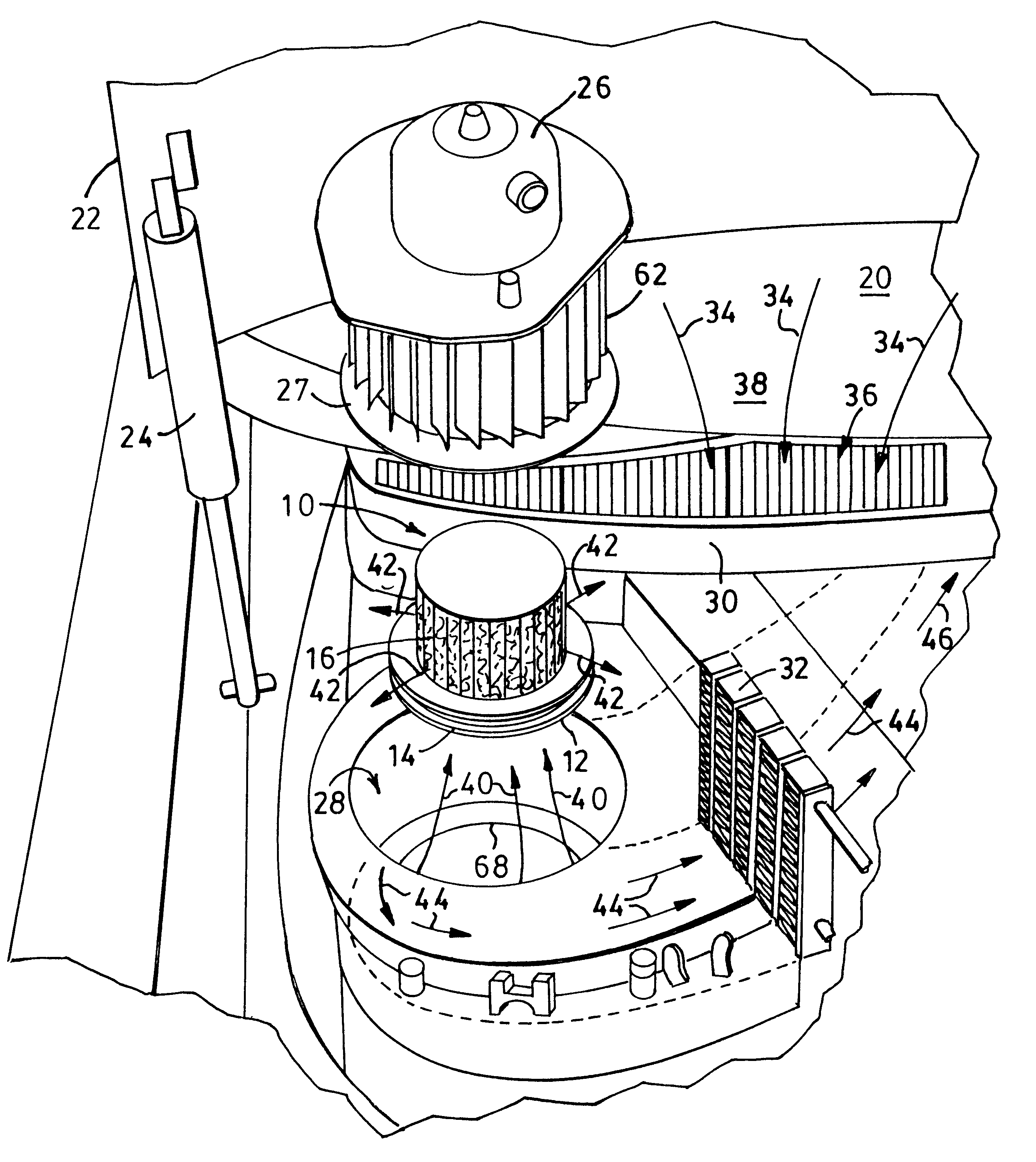
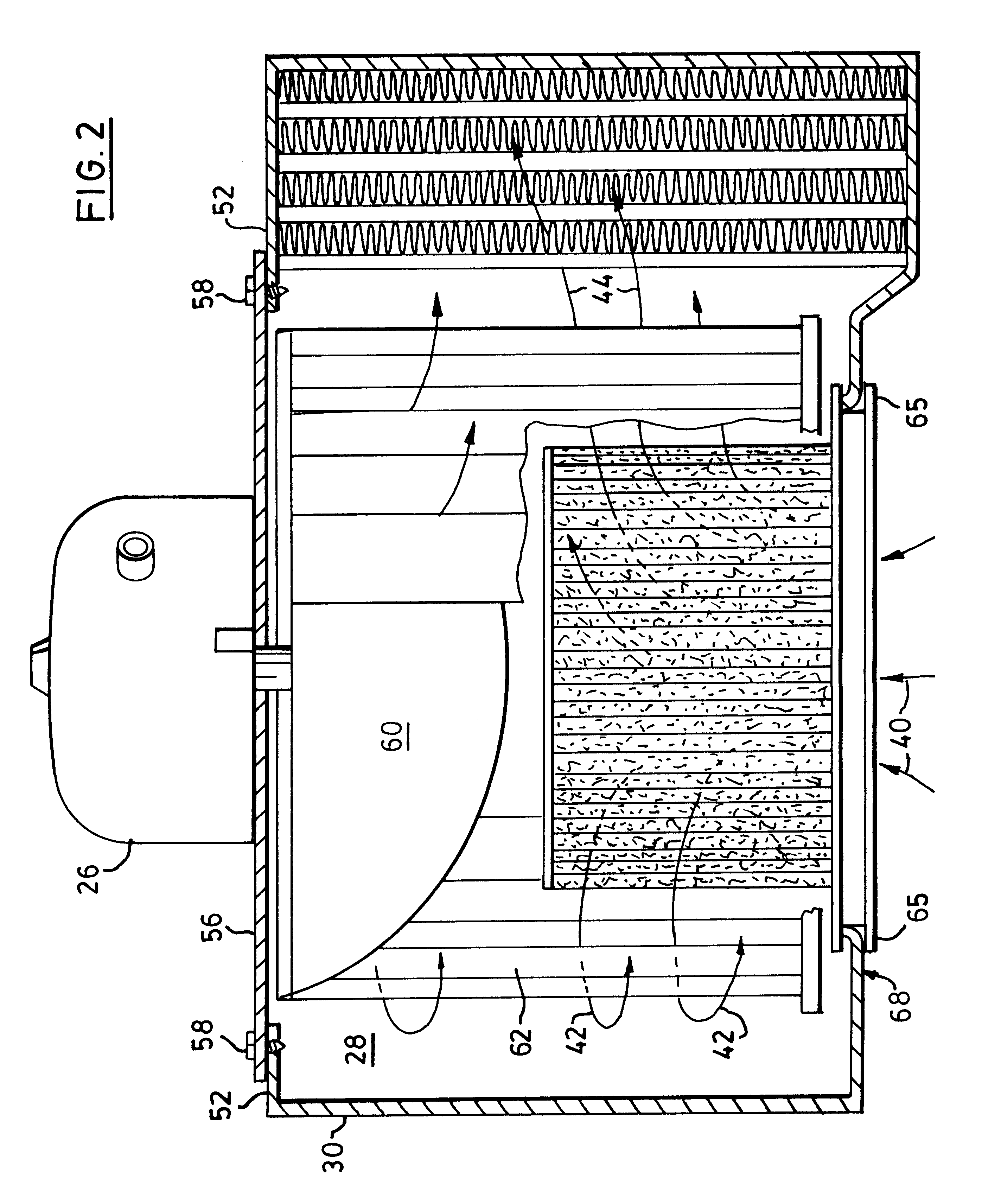
An air filtering device is shown generally as 10 in FIG. 1. The air filtering device includes a bottom base unit, shown generally as 12 which includes a perimeter mounting flange 14 and an air filter 16 which is retained in the bottom base unit 12. These elements are described in further detail below.
Also shown in FIG. 1 is a vehicle indicated generally as 20 which includes a hood 22 and a hood support cylinder 24. A blower motor assembly 26 is shown in exploded view above the air filtering device 10. The blower motor assembly 26 fits into a cavity 28 in the air circulation system of the vehicle 20. The air circulation system includes a cowl 30 which directs air past the blower 26, driving a fan 27, then a air condition core (or heat exchanger) 32 and then through conduits and into an interior portion of the vehicle 20.
The flow of air into the vehicle is shown by a number of arrows. Beginning with arrows 34, the air is taken in through an air intake screen 36 adjacent to the windshi...
PUM
| Property | Measurement | Unit |
|---|---|---|
| Length | aaaaa | aaaaa |
| Length | aaaaa | aaaaa |
| Flexibility | aaaaa | aaaaa |
Abstract
Description
Claims
Application Information
 - Generate Ideas
- Intellectual Property
- Life Sciences
- Materials
- Tech Scout
- Unparalleled Data Quality
- Higher Quality Content
- 60% Fewer Hallucinations
Browse by: Latest US Patents, China's latest patents, Technical Efficacy Thesaurus, Application Domain, Technology Topic, Popular Technical Reports.
© 2025 PatSnap. All rights reserved.Legal|Privacy policy|Modern Slavery Act Transparency Statement|Sitemap|About US| Contact US: help@patsnap.com