Method for identifying the presence and orientation of an object in a vehicle

a technology for identifying the presence and orientation of objects in vehicles, applied in the direction of pedestrian/occupant safety arrangements, instruments, and reradiation, etc., can solve the problems of excessive cost of replacing airbags, child in rear facing child seats placed on the right front passenger seat is in danger of being seriously injured or killed, and achieves the effect of suppressing the deployment of airbags

Inactive Publication Date: 2001-07-03
AMERICAN VEHICULAR SCI
View PDF38 Cites 67 Cited by
  • Summary
  • Abstract
  • Description
  • Claims
  • Application Information

AI Technical Summary

Benefits of technology

It is another broad object of the present invention to provide a method for accurately detecting the presence of a rear-facing child seat in order to prevent an airbag from deploying, which airbag would impact against the rear-facing child seat if deployed.
6. To provide a method for locating transducers within the passenger compartment at specific locations such that the highest reliability of classification of objects and their position is obtained from the signals generated by the transducers.

Problems solved by technology

As discussed in detail in one or more of the copending patent applications cross-referenced above, for a variety of reasons vehicle occupants may be too close to the airbag before it deploys and can be seriously injured or killed as a result of the deployment thereof.
Also, a child in a rear facing child seat which is placed on the right front passenger seat is in danger of being seriously injured if the passenger airbag deploys.
In addition to eliminating the disturbance and possible harm of unnecessary airbag deployments, the cost of replacing these airbags will be excessive if they all deploy in an accident needlessly.
Each of these systems will be discussed below and unfortunately have significant limitations.
White et al. correctly perceive that such a sensor could be defeated, and the airbag falsely deployed, by an occupant adjusting the control knobs on the radio and thus they suggest the use of a plurality of such sensors but do not disclose where they would be mounted, other than on the instrument panel below the steering wheel, or how they would be combined to uniquely monitor particular locations in the passenger compartment and to identify what is occupying those locations.
The object of an occupant out-of-position sensor is to determine the location of the head and / or chest of the vehicle occupant relative to the airbag since it is the impact of either the head or chest with the deploying airbag which can result in serious injuries.
Both such mounting locations are particularly prone to detection errors due to positioning of the occupant's hands, arms and legs.
Such a combination, however, would not differentiate between an occupant with both hands and arms in the path of the ultrasonic transmitter at such a location that they were blocking a substantial view of the occupant's head or chest.
In fact the closer that the occupant gets to the airbag the faster the inflation rate of the airbag is according to the Fujita patent, which thereby increases the possibility of injuring the occupant.
"Out-of-position" as used for an occupant means that the occupant, either driver or passenger, is sufficiently close to the airbag prior to deployment that he or she is likely to be more seriously injured by the deployment event itself than by the accident.
Such a system can be defeated if the driver is wearing glasses, particularly sunglasses, or another optical device which obstructs a clear view of his / her eyes.
Rather, Ando is limited to control of vehicle devices by responding to motion of the driver's mouth and eyes.
Again, Faris is only interested in locating the driver's eyes relative to the sun or oncoming headlights and does not identify or monitor the occupant or locate the occupant, a rear facing child seat or any other object for that matter, relative to the passenger compartment or the airbag.
Also, Faris does not use trainable pattern recognition techniques such as neural networks.
Similarly, the implementation of the techniques of the above referenced patents requires expensive microprocessors while the implementation with neural networks and similar trainable pattern recognition technologies permits the use of low cost microprocessors typically costing less than about $5.
It has been found in both of these cases that even though the proper identification is made in a high percentage of the cases, there are still a small but significant number of cases where an error in diagnosis is made based on the information received from the sensors.
These systems, although a significant improvement over the other prior art, still fail to achieve the very high reliability desired by the automobile manufacturers.

Method used


Image

  • Method for identifying the presence and orientation of an object in a vehicle
  • Method for identifying the presence and orientation of an object in a vehicle
  • Method for identifying the presence and orientation of an object in a vehicle

Examples


Embodiment Construction

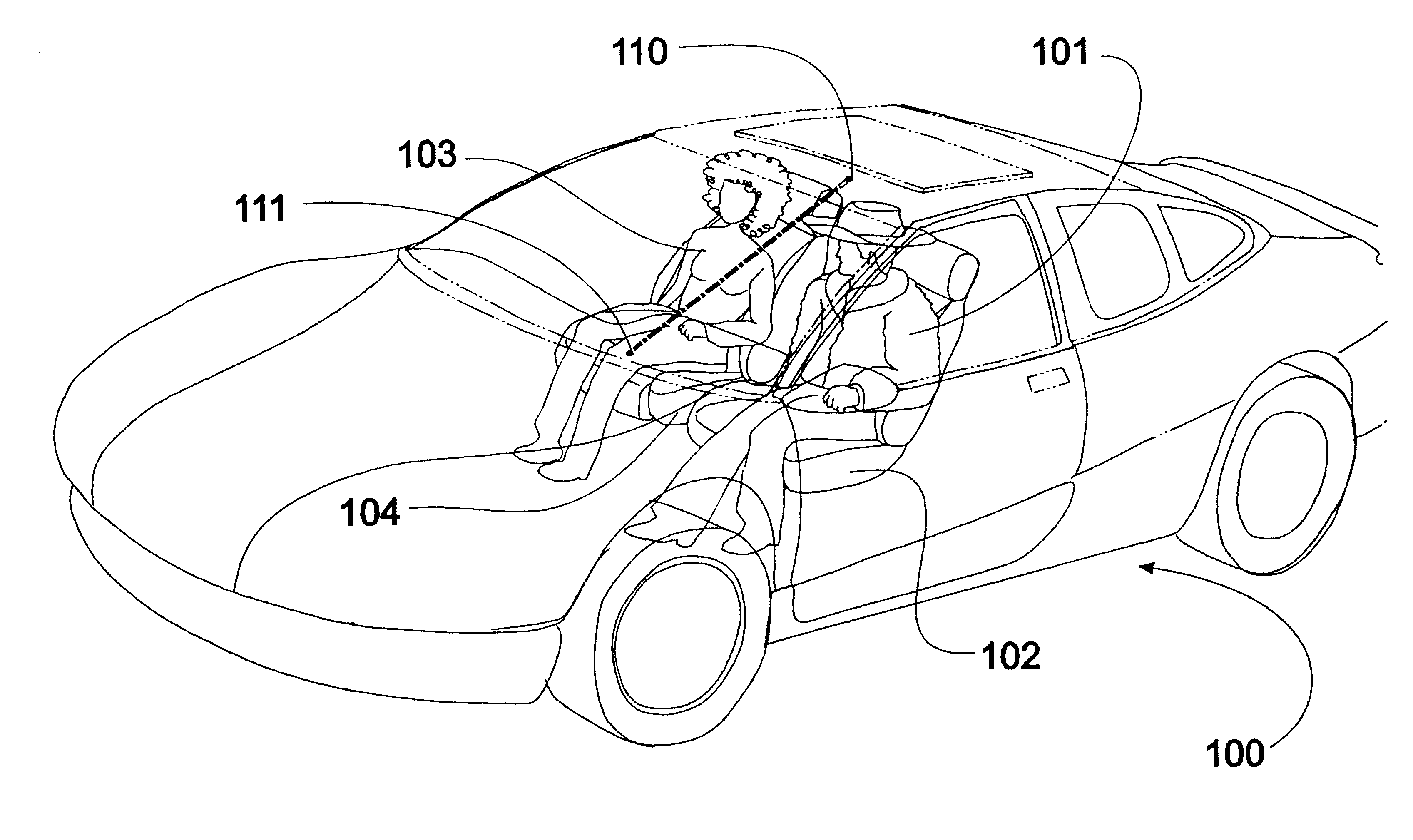
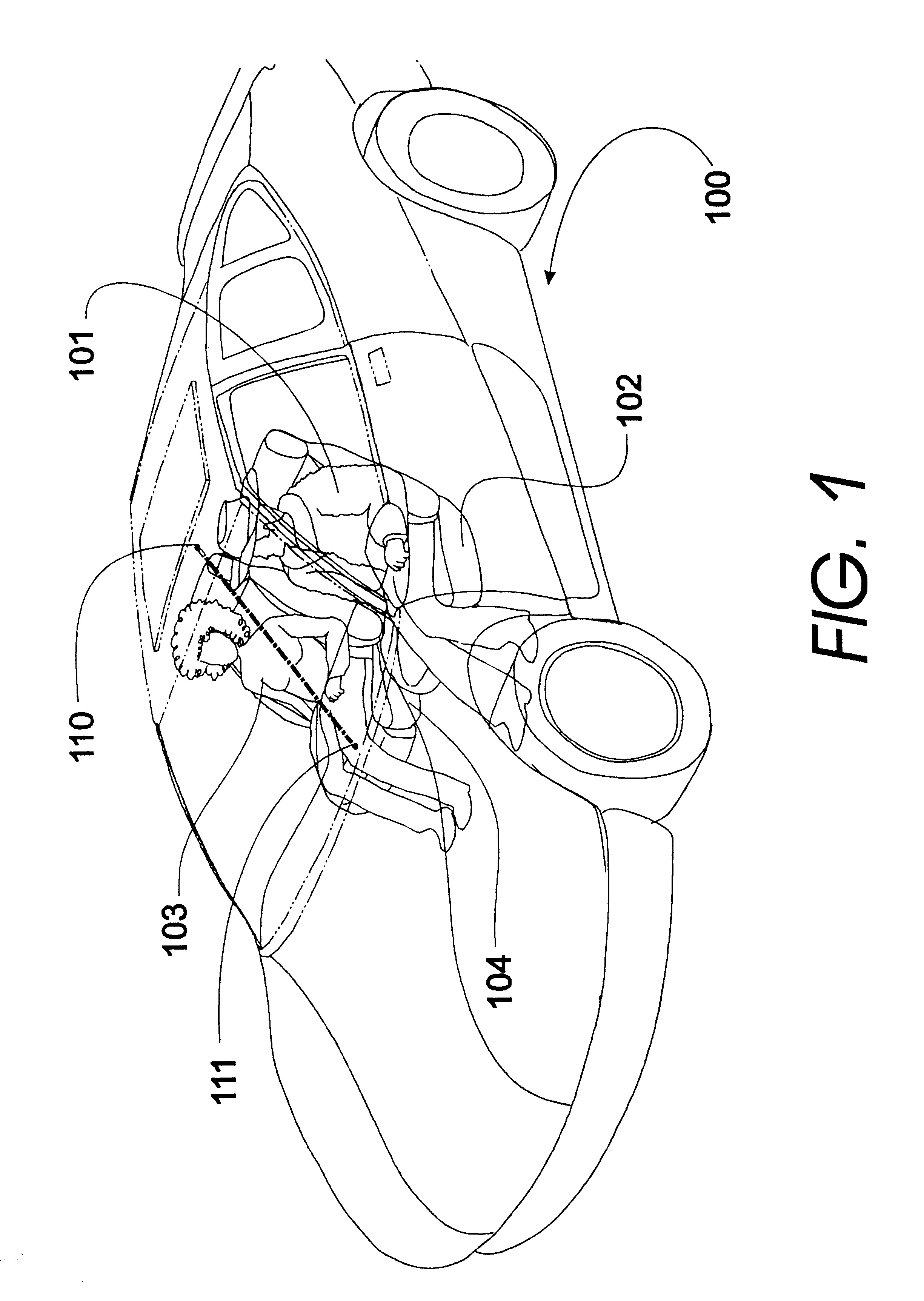
Referring now to the drawings, where like reference numbers represent like or similar parts, a section of the passenger compartment of an automobile is shown generally as 100 in FIG. 1. A driver 101 of a vehicle sits on a seat 102 behind a steering wheel, not shown, and an adult passenger 103 sits on seat 104 on the passenger side. Two transmitter and receiver assemblies 110 and 111, also referred to herein as transducers, are positioned in the passenger compartment 100, one transducer 110 is arranged on the headliner adjacent or in proximity to the dome light and the other transducer 111 is arranged on the center of the top of the dashboard (the methodology leading to the placement of these transducers is central to the instant invention as explained in detail below). In this situation, the invention will reliably detect that an occupant is sitting on seat 104 and deployment of the airbag is enabled in the event that the vehicle experiences a crash. Transducers 110,111 are placed w...


PUM


Abstract

A method for determining the location of an object in a passenger compartment of a vehicle in which ultrasonic waves are transmitted from a first transducer into the passenger compartment, waves reflected off an object in the passenger compartment are received by the first transducer and a first distance from the first transducer to the object is calculated based on the time difference between the transmitted waves and reflected waves when received by the first transducer. Further, different ultrasonic waves are transmitted from a second transducer into the passenger compartment which then receives reflected waves off the object and a second distance from the second transducer to the object is calculated based on the time difference between the transmitted waves and reflected waves when received by the second transducer. The approximate location of the object in the passenger compartment is determined based on the first distance and the second distance.

Description

This application is related to: (i) U.S. patent application Ser. No. 08 / 505,036 now U.S. Pat. No. 5,653,462, entitled "Vehicle Occupant Position And Velocity Sensor" filed Jul. 21, 1995, which is a continuation of U.S. patent application Ser. No. 08 / 040,978 now abandoned, filed Mar. 31, 1993, which in turn is a continuation of U.S. patent application Ser. No. 07 / 878,571 now abandoned, filed May 5, 1992; (ii) U.S. patent application Ser. No. 08 / 239,978 now abandoned, entitled "Vehicle Interior Identification and Monitoring System" filed May 9, 1994; (iii) U.S. patent application Ser. No. 08 / 474,786 now U.S. Pat. No. 5,845,000, entitled "Optical Identification and Monitoring System Using Pattern Recognition for use with Vehicles" filed Jun. 7, 1995; (iv) U.S. patent application Ser. No. 08 / 474,783 now U.S. Pat. No. 5,822,707, entitled "Automatic Vehicle Seat Adjuster" filed Jun. 7, 1995; (v) U.S. patent application Ser. No. 08 / 474,784 now U.S. Pat. No. 5,748,473, entitled "Automatic V...

Claims


Application Information

Patent Timeline
Patent Type & Authority Patents(United States)
IPC IPC(8): B60R21/01G01S15/04G01S15/42G01S15/00G06K9/00G01S15/88B60R21/015
CPCG01S15/04G01S15/42B60R21/01536G06K9/00362G01S15/88G06V40/10
Inventor VARGA, ANDREW J.BREED, DAVID S.DUVALL, WILBUR E.
Owner AMERICAN VEHICULAR SCI
Why Eureka
Try Eureka