Precision direct drive mechanism for a power assist apparatus for a bicycle

a direct drive, bicycle technology, applied in the direction of vehicle components, rider propulsion, vehicle transmission, etc., can solve the problems of excessive wear and noise, difficult reengagement of direct drive power assist devices for bicycles, and general requirements for complex gearing arrangements, etc., to achieve fast conversion, maintain precision alignment, and reduce weight penalty

Inactive Publication Date: 2002-03-19
CURRIE ACQUISITIONS LLC
View PDF27 Cites 30 Cited by
  • Summary
  • Abstract
  • Description
  • Claims
  • Application Information

AI Technical Summary

Benefits of technology

A further objective of this invention is to obtain a practical direct drive gear system employing precision indexing and alignment which is in a self-contained bicycle rear wheel assembly that features: (1) precision alignment with repeated removal and reengagement of rear wheel for repair; (2) maintaining precision alignment in all rough environments; and (3) has fast conversion of non-electric to electric configuration (<3 minutes) and back again with minimal weight penalty in normal operation.
A further ...

Problems solved by technology

The prior art direct drive power assist devices for a bicycle have generally required complex gearing arrangements.
Upon removal of the wheel for maintenance, such as tire repair, precise reengagement is difficult leading to excessive wear and noise during operation.
Also, complex gearing arrangements are difficult to maintain in precise alignment when the bicycle encounters road bumps and holes.
Also, incorporation of prior art power assist apparatuses on bicycles has made it difficult to ...

Method used


Image

  • Precision direct drive mechanism for a power assist apparatus for a bicycle
  • Precision direct drive mechanism for a power assist apparatus for a bicycle
  • Precision direct drive mechanism for a power assist apparatus for a bicycle

Examples


Embodiment Construction

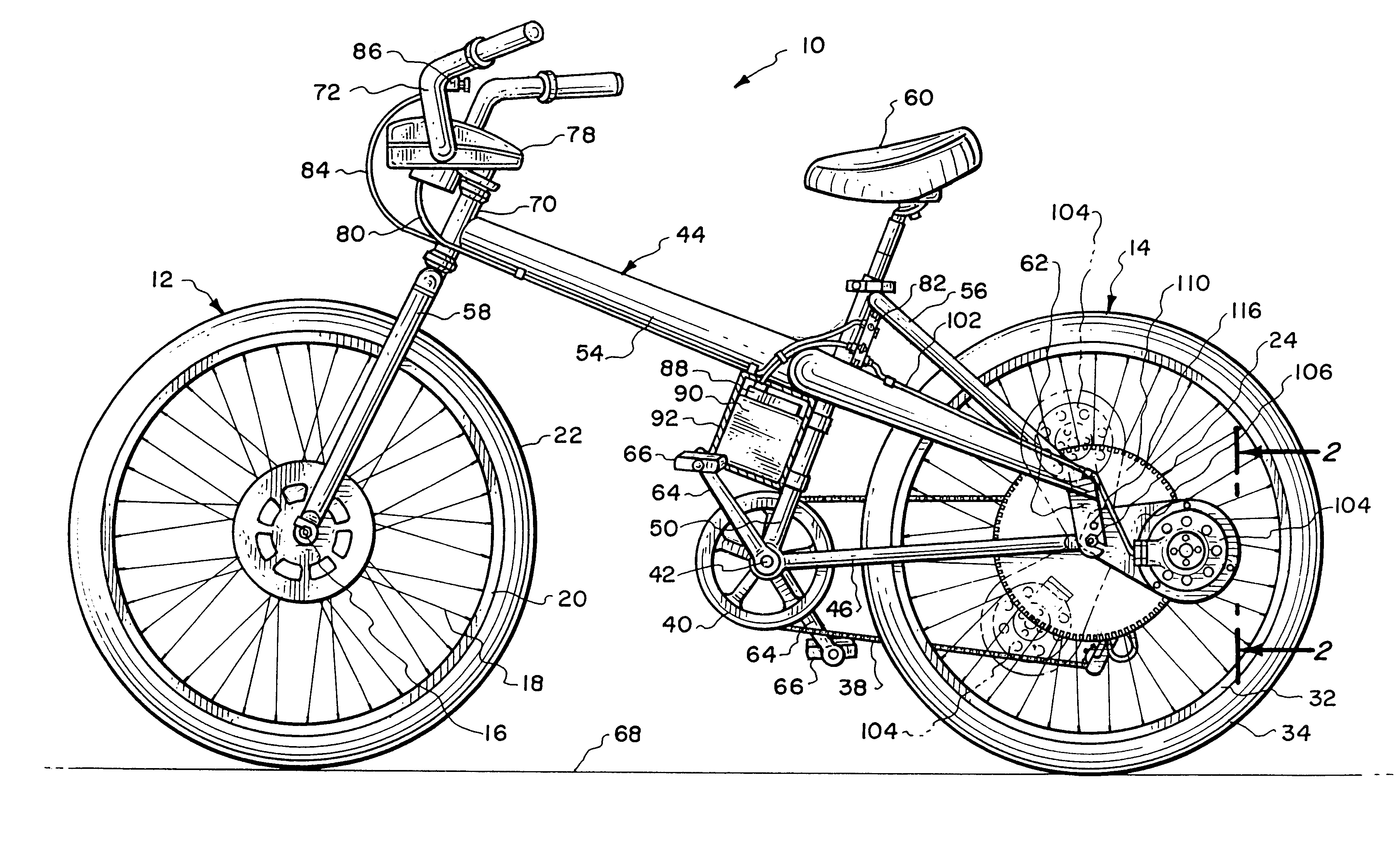
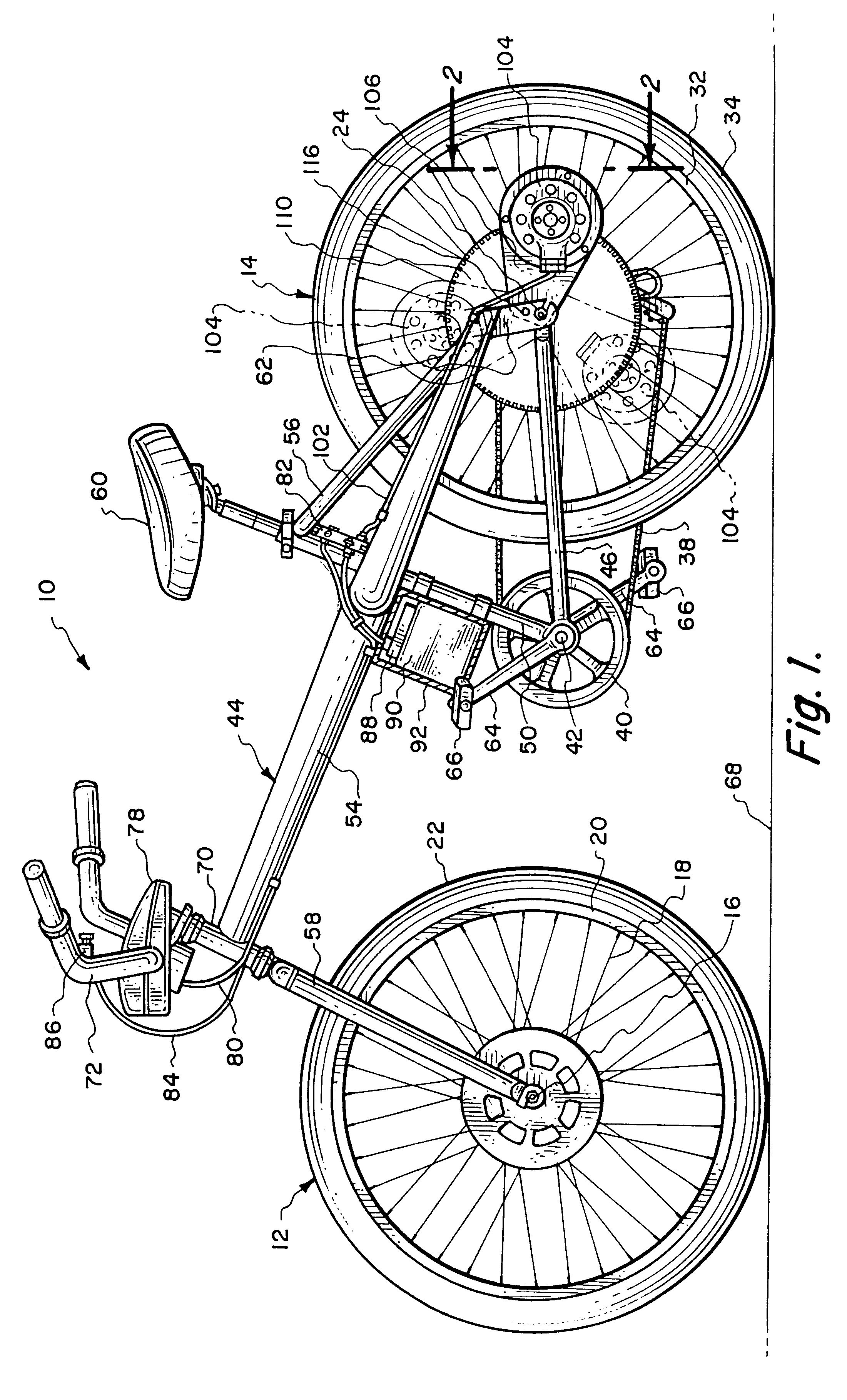
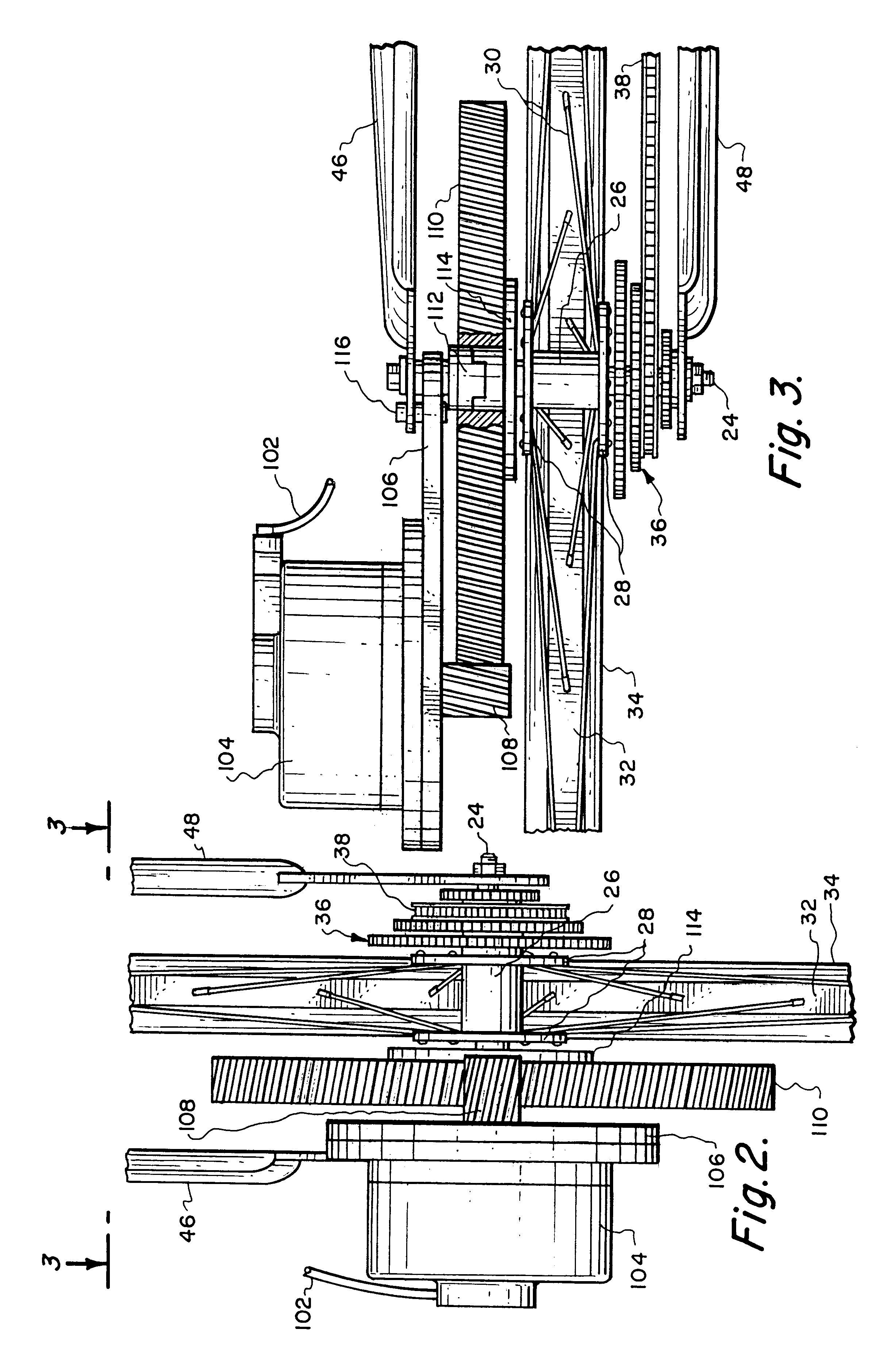
This invention is described in relation to a bicycle. However, it is understood that this invention could be used not only on a bicycle type vehicle that has two support wheels but also a bicycle type vehicle that has three or four support wheels. The word bicycle will be understood to include all such vehicles. The power assist apparatus could utilize an exterior gear connection, which is shown in the drawings, or could utilize an internal gearing arrangement mounted within the hub of the support wheel on which the motor of the power assist apparatus is mounted. Also, instead of gears, a chain or belt drive could be used.

Referring particularly to the drawings, there is shown a bicycle 10 having a front wheel 12 and a rear wheel 14. The rear wheel 14 is rotatable solely within a plane of rotation. The front wheel 12 includes an axle 16 from which extends a plurality of wire spokes 18. The wire spokes 18 are affixed to a tire rim 20 on which is mounted a rubber tire 22. In a similar ...


PUM


Abstract

A power assist apparatus which includes a battery pack that connects with a motor housing with the battery pack being removably mounted on the frame of the bicycle and the motor housing being mounting on a mounting plate which is carried by one of the support wheels of the bicycle. The power assist apparatus is designed to not only assist in the manual operation of the bicycle but also as a sole source of power for the bicycle. The mounting plate is to be affixed to the frame of the bicycle upon the desired location being selected for the mounting plate. The motor assembly operates a drive gear, pulley or sprocket which connects to a driven gear, pulley or sprocket which is mounted in conjunction with one of the support wheels of the bicycle. The motor housing may be disconnectable from the mounting plate as also the battery pack is capable of being disengaged from the frame of the bicycle permitting the bicycle to be used as a conventional bicycle without the power assist apparatus. The motor assembly is indexed to the axle of the support wheel maintaining accurate alignment in all operating conditions and upon repeated engagements and disengagements of the support wheel from the bicycle frame.

Description

BACKGROUND OF THE INVENTION1. Field of the InventionThis invention relates to an electrically operated, by means of a battery, power assist apparatus for a bicycle and more particularly, to a new and novel construction of that power assist apparatus for a bicycle.2. Description of the Prior ArtElectric powered bicycle have long been known. All electric powered bicycles incorporate an electric motor which is powered by a battery. One way the bicycle is powered is by a motor that operates through a drive wheel which frictionally engages with a support wheel of the bicycle. Movement of the drive wheel adds power to the manual movement of the bicycle or could be the only source of movement of the bicycle. Frictional engagement between the drive wheel and a support wheel is only one method. Others involve many configurations of direct drive involving shafts, chains, and gears but with the common feature of the driving motor being mounted on the bicycle frame in one position or another (e...

Claims


Application Information

Patent Timeline
IPC IPC(8): B62M23/02B62M6/60B62M6/40
CPCB62M6/60
Inventor MAYER, RICHARD A.CURRIE, MALCOLM R.
Owner CURRIE ACQUISITIONS LLC
Why Eureka
Try Eureka