System, method and apparatus for windblast reduction during release or ejection from aircraft

a technology of windblast and release or ejection, which is applied in the direction of aircraft ejection means, emergency apparatus, launching weapons, etc., can solve the problems of particularly common snap back neck injuries, facial and/or eye tissue damage, etc., to reduce the impact of flowfield forces, reduce the probability of injury-free or low-injury ejection, and reduce the weight penalty of aircraft from incorporating the invention

Active Publication Date: 2009-12-31
LOCKHEED MARTIN CORP
View PDF16 Cites 2 Cited by
  • Summary
  • Abstract
  • Description
  • Claims
  • Application Information

AI Technical Summary

Benefits of technology

[0007]Embodiments of a system, method and apparatus for reducing the impact of flowfield forces on objects released, launched or jettisoned from high speed aircraft during flight are disclosed. For example, the invention provides a solution for overcoming ejection windblast injuries to pilots and increases the probability of injury-free or low-injury ejection. Weight penalties to the aircraft from incorporating the invention are minimal when measured against the potential reduction in ejection windblast injury. The invention also is suitable for reducing the intensity of flowfield forces that act on objects released from aircraft, such as bombs and missiles on military aircraft.

Problems solved by technology

When aircraft pilots are forced to eject from cockpits at very high air speeds, they are subjected to instantaneous and near-lethal aerodynamic forces from the air flowfield coming over the canopy.
Snap back neck injuries and facial and / or eye tissue damage are particularly common due to the body trajectory during ejection insertion into the flowfield and the fact that the head, helmet and visor enter the flowfield before the rest of the body.
These factors create highly asymmetric and dangerous aerodynamic loading on the pilots body.
However, the local flowfield over the top of the canopy that impacts the ejecting pilot can approach 650 knots or more (i.e., about Mach 1.06 at 20,000 feet), creating an almost unsurvivable ejection environment for pilots.
When the ordnance is released, the flowfields can tend to force the ordnance back toward the aircraft, which can create hazardous conditions for the aircraft and pilot as well as damage the ordnance or affect its mission.

Method used


Image

  • System, method and apparatus for windblast reduction during release or ejection from aircraft
  • System, method and apparatus for windblast reduction during release or ejection from aircraft
  • System, method and apparatus for windblast reduction during release or ejection from aircraft

Examples


Embodiment Construction

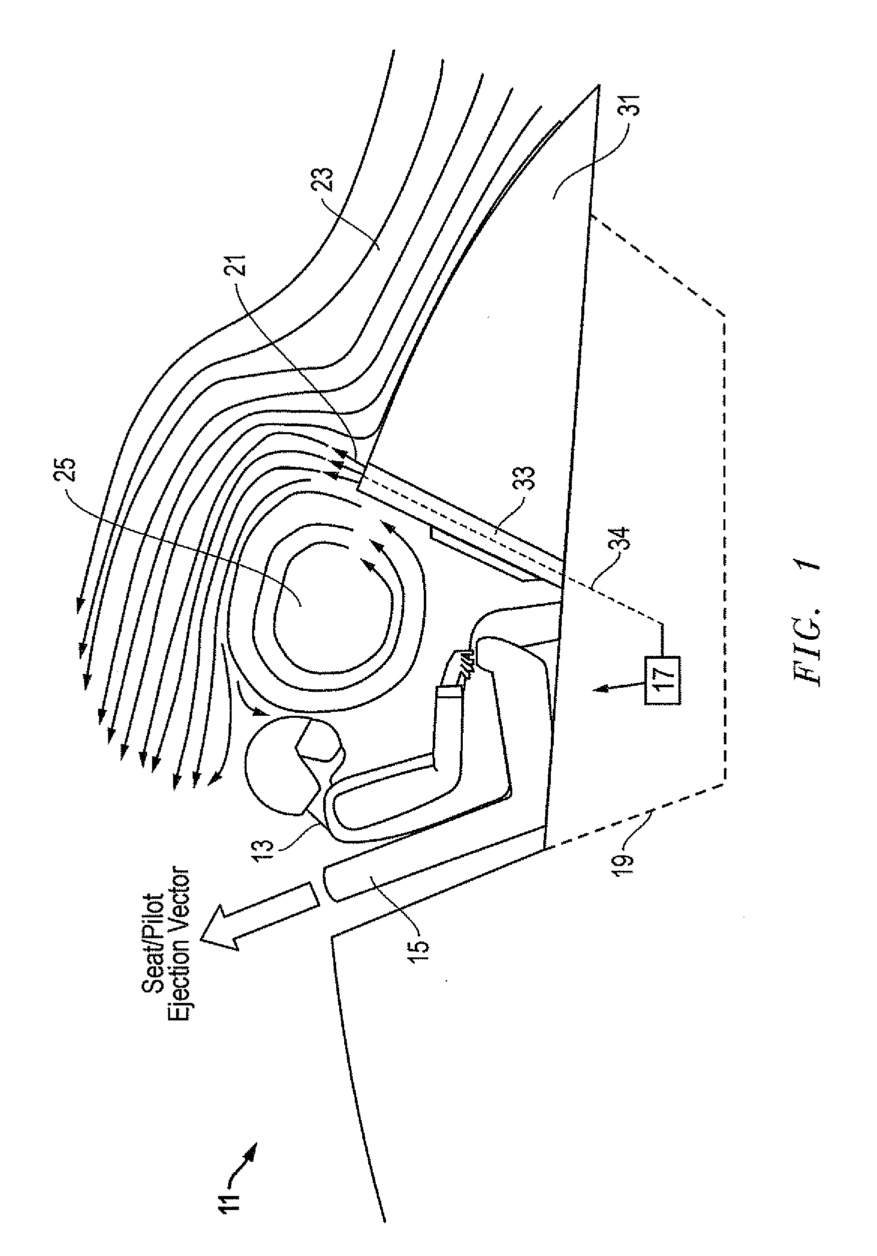
[0018]Referring to FIGS. 1-5, embodiments of a system, method and apparatus for reducing the impact of flowfield forces on objects released, launched or jettisoned from high speed aircraft during flight are disclosed. Although the invention is primarily depicted and described in FIGS. 1-3 and 5 as providing a solution for overcoming ejection windblast injuries to pilots and increases the probability of injury-free or low-injury ejection, the invention has still other applications. For example, as shown in FIG. 4, the invention also is suitable for reducing the intensity of flowfield forces that act on other types of objects that are released or launched from aircraft, such as bombs, missiles, fuel tanks, etc.

[0019]In one embodiment, the invention comprises a system for reducing the impact of flowfield forces on objects ejected or launched from an aircraft during flight. FIG. 1 illustrates an aircraft 11 having an object (e.g., a pilot 13 in a seat 15) releasably mounted to the aircr...


PUM


Abstract

The invention reduces the impact of flowfield forces on objects launched from high speed aircraft during flight. For example, the invention provides a solution for overcoming ejection windblast injuries to pilots and increases the probability of injury-free or low-injury ejection. The gas flow is used to rapidly create a very short duration protective “bubble” in the incoming air flow ahead of the ejecting pilot. The bubble reduces the local flow velocity and aerodynamic forces on the pilot during the injury-critical time period of ejection. The invention also is suitable for reducing the intensity of flowfield forces that act on released military aircraft ordnance, such as bombs and missiles.

Description

BACKGROUND OF THE INVENTION[0001]1. Technical Field[0002]The present invention relates in general to releasing objects from aircraft during high speed flight and, in particular, to an improved system, method and apparatus for reducing windblast injuries to pilots when they eject from the cockpit of a high speed aircraft.[0003]2. Description of the Related Art[0004]When aircraft pilots are forced to eject from cockpits at very high air speeds, they are subjected to instantaneous and near-lethal aerodynamic forces from the air flowfield coming over the canopy. Snap back neck injuries and facial and / or eye tissue damage are particularly common due to the body trajectory during ejection insertion into the flowfield and the fact that the head, helmet and visor enter the flowfield before the rest of the body. These factors create highly asymmetric and dangerous aerodynamic loading on the pilots body.[0005]At near-transonic speeds, the probability of ejection survival without serious injur...

Claims


Application Information

Patent Timeline
Patent Type & Authority Applications(United States)
IPC IPC(8): B64D25/115B64D1/12
CPCB64D1/04B64D25/10B64D25/02
Inventor JONES, MIKE I.BAIRD, GLENN W.CHARLTON, ERIC F.
Owner LOCKHEED MARTIN CORP
Why Eureka
Try Eureka