Hybrid drive powered lift platform

a technology of powered lift platforms and hybrid drive, which is applied in the direction of toy aircraft, vertical landing/take-off aircraft, aircraft navigation control, etc., can solve the problems of turbine engines, although more efficient, and the platform cannot be automatically rotated, so as to achieve the effect of minimal weight penalties and enhanced lift characteristics

Active Publication Date: 2007-06-19
AEROFEX
View PDF10 Cites 17 Cited by
  • Summary
  • Abstract
  • Description
  • Claims
  • Application Information

AI Technical Summary

Benefits of technology

[0007]The present invention provides a thrust recovery system for use in a powered lift platform utilizing fixed-pitch propellers. The thrust recovery system of the invention is a compressed air-based system which enhances the lift characteristics of the platform with minimal weight penalties. The system utilizes an air compressor coupled to the drive motor of the platform and an on-board, high pressure tank for air storage. The fixed-pitch propellers are coupled to the primary drive system with over-running clutches, thus allowing the thrust recovery system to rotate the propellers faster than if driven solely by the primary drive system. Preferably the propellers are surrounded by air ducts.
[0008]In one embodiment of the invention, the thrust recovery system uses cold air jets mounted at the tips of the propellers, i.e., tip jets, to rotate the propellers. The tip jets on each propeller can be under the control of a single valve, thus providing an extremely simple design, or under the control of multiple independent valves, thus providing a means of achieving single axis attitude control. In addition to the tip jets, the air-based system can be coupled to a circulation control system comprised of a plurality of holes within either the trailing edge or the leading edge of the propeller blades, thus providing a means of increasing the coefficient of lift. As with the tip jets, valves can be used to allow either simultaneous control, or independent control, of the circulation control system contained within each propeller. Alternately, or in addition to the tip jets and the circulation control system, the air tank of the thrust recovery system can be coupled to one or more perforated tubing segments surrounding at least a portion of the platform's air ducts, thereby providing a means of overcoming the effects of sudden wind gusts.

Problems solved by technology

In general, ducted propeller platforms do not possess autorotation capabilities.
Unfortunately as such an approach does not provide complete system redundancy, the failure of any of a variety of other components within the drive system will still lead to the catastrophic failure of the platform.
As a result, however, such a platform must use an internal combustion engine since turbine engines, although more efficient, suffer from spin-up lag.
Although the inherent lag in turbines can be overcome using variable-pitch propellers, this defeats the mechanical simplicity and the weight savings offered by the used of fixed-pitch propellers.
Another issue confronting ducted propellers is their susceptibility to upsets due to sudden wind gusts.
Although a variety of fixed-pitch propeller platforms have been designed, these platforms typically require the use of internal combustion engines, provide limited fail-safe operation, and are susceptible to wind gusts.

Method used


Image

  • Hybrid drive powered lift platform
  • Hybrid drive powered lift platform
  • Hybrid drive powered lift platform

Examples


Embodiment Construction

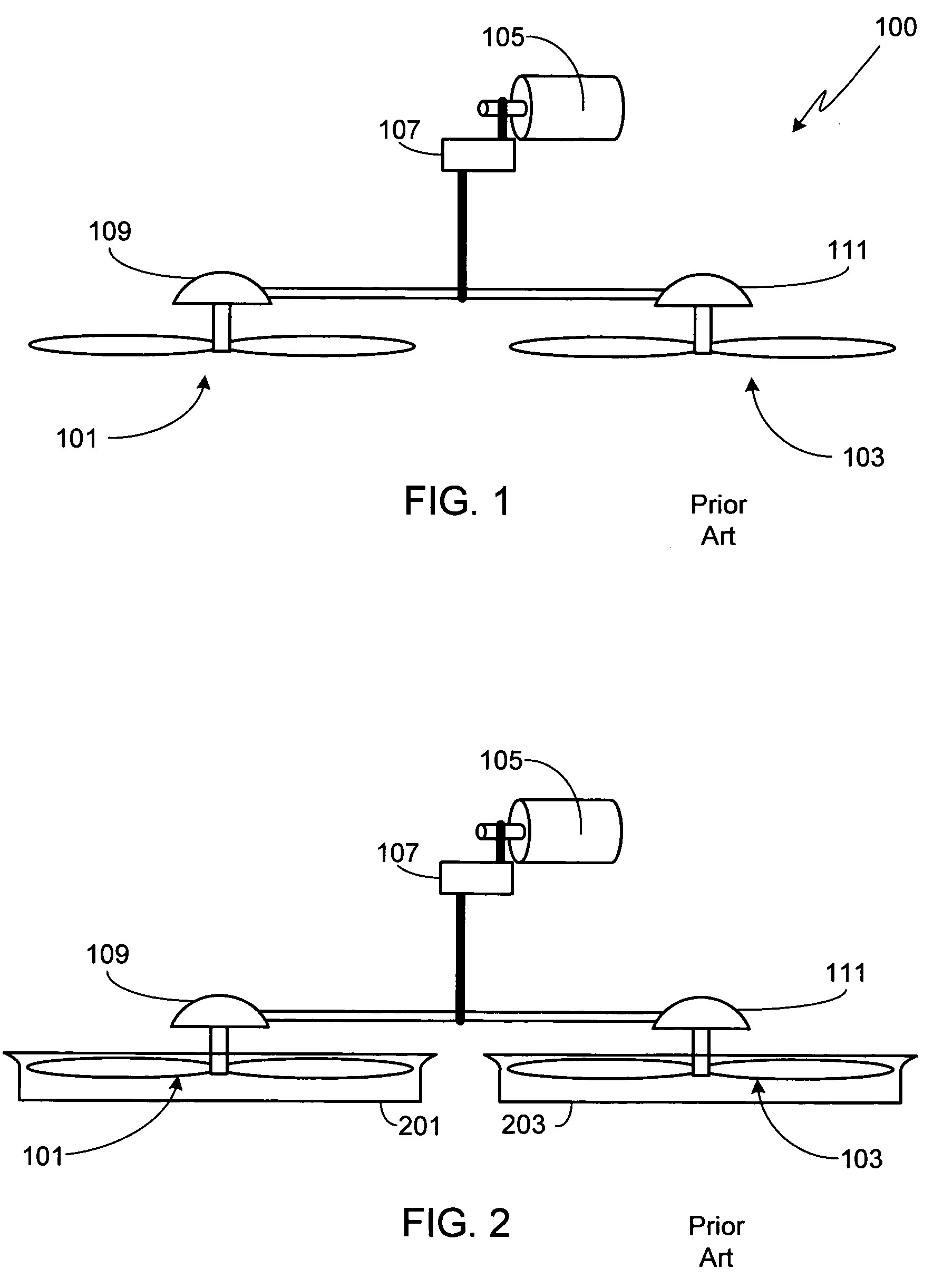
[0024]FIG. 1 is a simplified view of a dual propeller powered lift platform according to the prior art. In this figure, as well as those that follow, the required control system is not shown as there are a variety of suitable control systems that are well known by those of skill in the art and which can be used with the prior art platform as well as the invention.

[0025]As shown, platform 100 utilizes a pair of fixed-pitch propellers 101 / 103 that are counter-rotating to offset yaw effects. Propellers 101 / 103 are coupled to an engine 105 via a transmission 107 and a pair of gearboxes 109 / 111 (e.g., ninety degree gearboxes). If desired, propellers 101 / 103 can be enclosed within a pair of aerodynamic ducts 201 / 203 as shown in FIG. 2. Ducts 201 / 203 increase the efficiency of propellers 101 / 103, thus increasing the lift of the platform for a given propeller diameter and engine power. Additionally, by eliminating the exposed blades of the propellers, the ducts substantially increase the sa...


PUM


Abstract

An air-based thrust recovery system for use in a powered lift platform utilizing fixed-pitch propellers is provided. The system utilizes an air compressor coupled to the drive motor of the platform and an on-board, high pressure tank for air storage. The fixed-pitch propellers are coupled to the primary drive system with over-running clutches, thus allowing the thrust recovery system to rotate the propellers faster than if driven solely by the primary drive system. Preferably the propellers are surrounded by air ducts. The thrust recovery system uses individually, or in combination, cold air jets mounted at the tips of the propellers, a circulation control system which blows out the leading or trailing edge of the propellers, and one or more perforated tubing segments surrounding at least a portion of the platform's air ducts.

Description

FIELD OF THE INVENTION[0001]The present invention relates generally to powered lift platforms and, more particularly, to an apparatus for augmenting the lift capabilities of the primary drive system in a dual propeller platform.BACKGROUND OF THE INVENTION[0002]A variety of propeller based lift platforms have been designed over the years which use two or more propellers coupled to a single engine. Typically the propellers are ducted, thus increasing propeller efficiency, decreasing noise and eliminating the dangers associated with exposed blades.[0003]In general, ducted propeller platforms do not possess autorotation capabilities. In order to achieve at least a level of fail-safe operation, such platforms often employ redundant engines thus allowing the platform to overcome the failure of a single engine. Unfortunately as such an approach does not provide complete system redundancy, the failure of any of a variety of other components within the drive system will still lead to the cat...

Claims


Application Information

Patent Timeline
Patent Type & Authority Patents(United States)
IPC IPC(8): B60V1/00B60V1/11B64C15/00B64C27/00
CPCA63H27/12B64C39/028B64C2201/027B64C2201/108B64U10/13B64U30/20
Inventor DE ROCHE, MARK STEPHEN
Owner AEROFEX
Why Eureka
Try Eureka