
Hard sectoring circuit and method for a rotating disk data storage device

a data storage device and hard sectoring technology, applied in the direction of maintaining head carrier alignment, recording signal processing, instruments, etc., can solve the problems of affecting the use of address marks on the disk, unable to retrieve sector data, and unable to achieve the effect of maximizing data storag

Inactive Publication Date: 2002-08-13
RES INVESTMENT NETWORK
View PDF14 Cites 3 Cited by
  • Summary
  • Abstract
  • Description
  • Claims
  • Application Information

AI Technical Summary

Problems solved by technology

The use of address marks on a disk suffers from the disadvantage that the marks can be lost for any of a number of reasons; for example, through flaws in the magnetic medium in which the data is written or accidental turn on of a write gate, used to enable writing, as a transducer head passes over an address mark.
That sector's data can never be retrieved because the controller will never receive the pulses necessary for locating the sector.
Similarly, read errors while searching for the address mark may cause a sector to be missed and lower the throughput of the data storage device.
The problem is exacerbated by other requirements placed on a rotating disk data storage system.
As a result, it has been necessary in the past to either forego recording tracks at different frequencies or use address marks, despite the disadvantage of much lower data security.

Method used


Image

  • Hard sectoring circuit and method for a rotating disk data storage device
  • Hard sectoring circuit and method for a rotating disk data storage device
  • Hard sectoring circuit and method for a rotating disk data storage device

Examples


Embodiment Construction

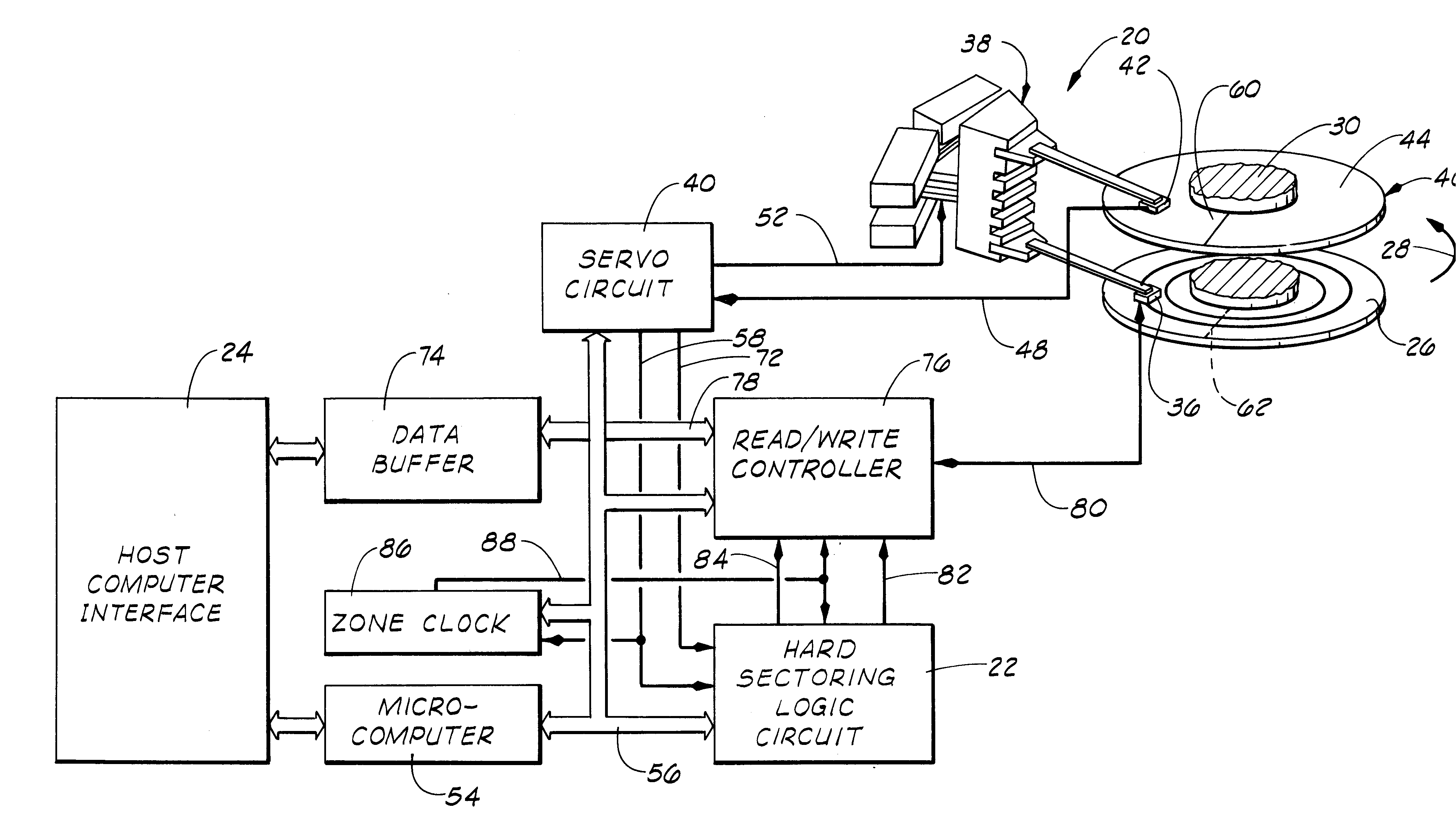
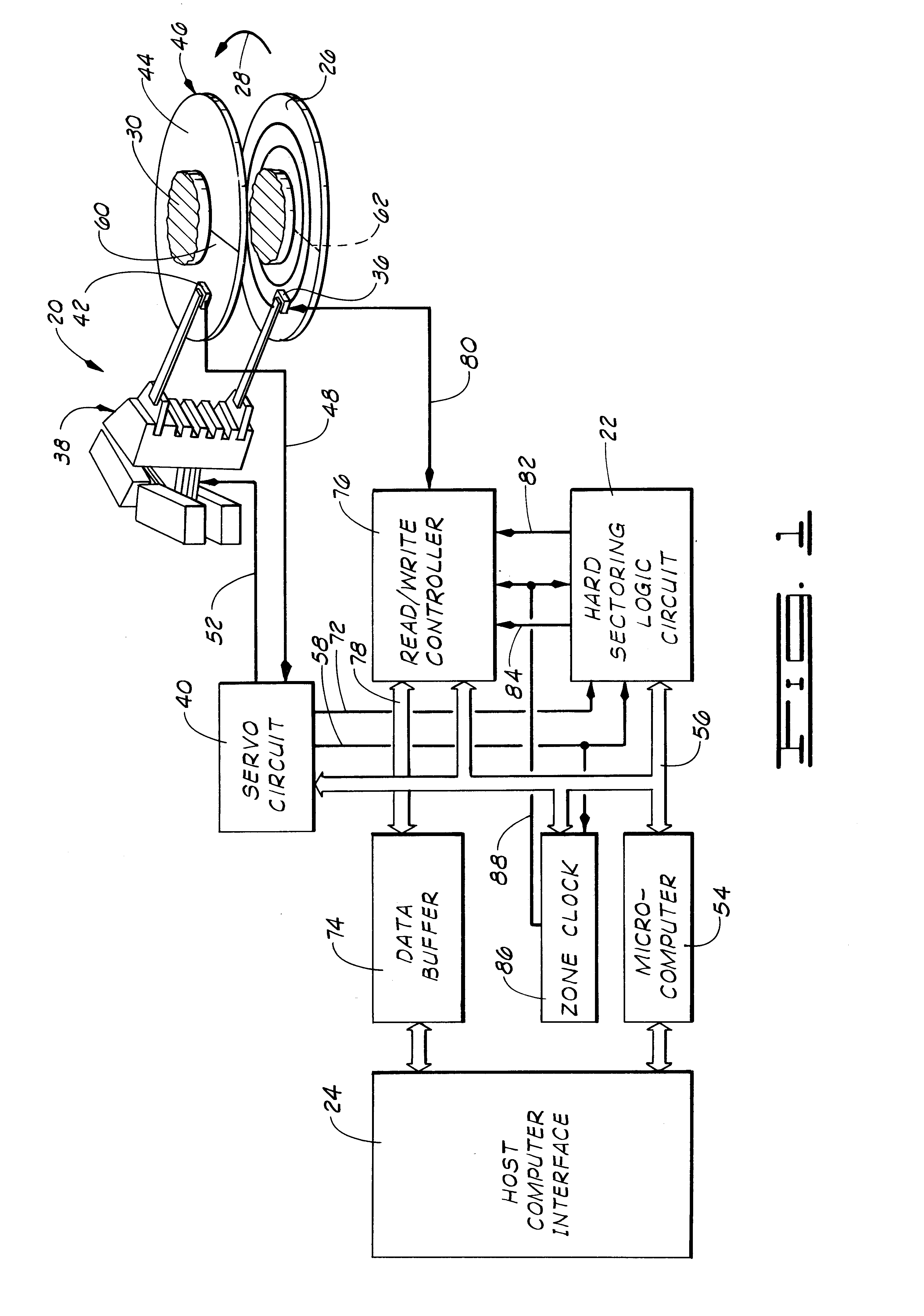
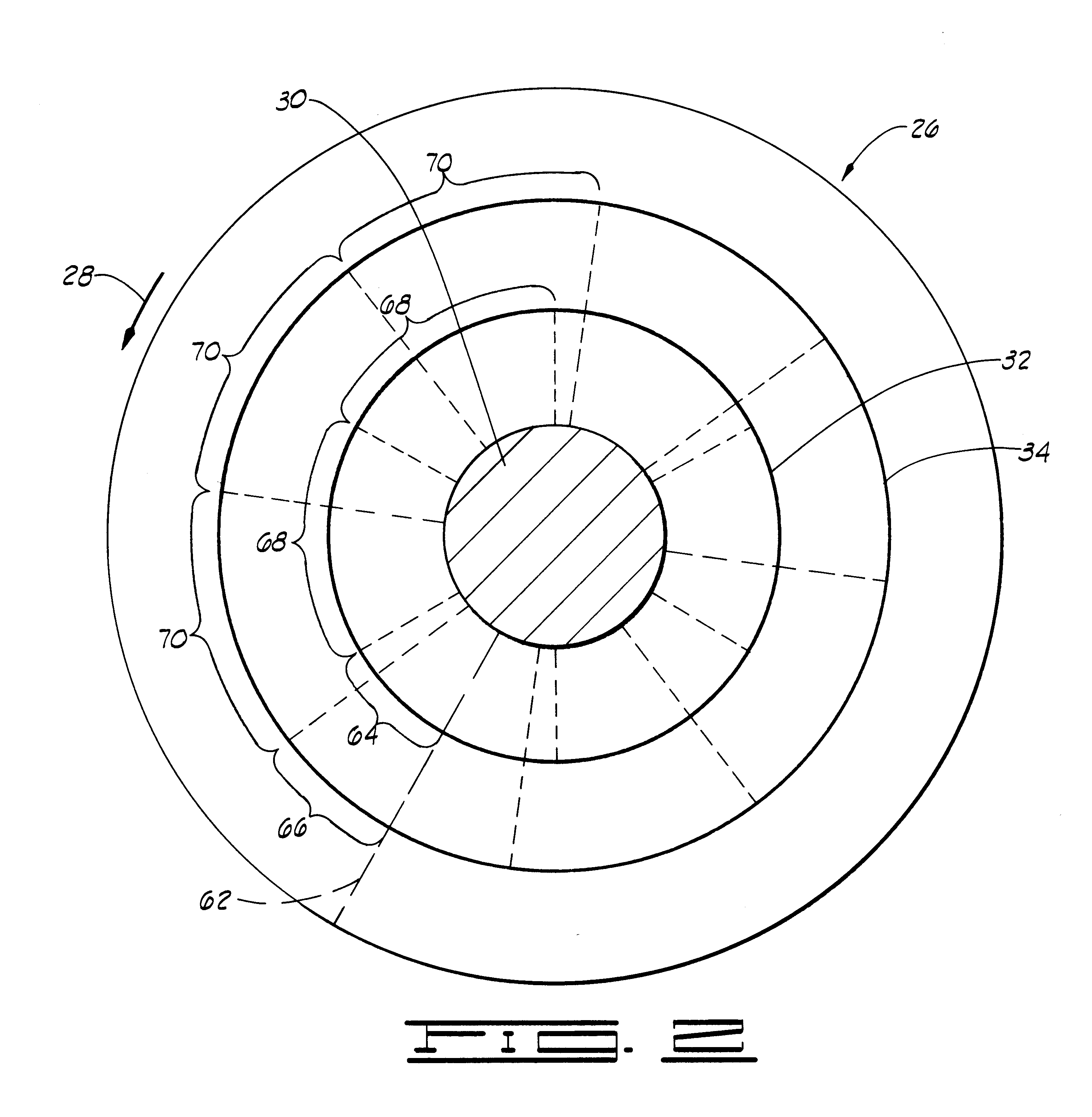
Referring now to the drawings in general and to FIGS. 1 and 2 in particular, shown therein and designated by the general reference number 20 is a rotating disk data storage device including a hard sectoring logic circuit 22 constructed in accordance with the present invention. As is conventional, the data storage device 20 is constructed to receive information from a host computer (not shown) via an interface 24 and store the information on a data storage disk, such as the disk 26 shown in FIGS. 1 and 2, that rotates in the direction indicated at 28 on a spindle 30. (As is known in the art, the device 20 will be comprised of a plurality of data storage disks. For clarity of illustration, only one data storage disk has been shown in the drawings.) Subsequently, the information is read from the disk 26 and returned to the host computer via the interface 24.

As shown in FIG. 2, the information received from the host computer is written to angularly extending sectors on concentric data t...


PUM

PropertyMeasurementUnit
rotation rateaaaaaaaaaa
angular distanceaaaaaaaaaa
timeaaaaaaaaaa

Abstract

An apparatus for providing sector location pulses to a controller of a rotating disk data storage device having a counter clocked in proportion to the disk rotation rate and an accumulator for accumulating times to sectors on the disk. A comparator connected to the counter and the accumulator enables an accumulator clock for repetitive clocking of the accumulator at such times the contents of the accumulator do not exceed the contents of the counter. A sector location pulse generator connected to the comparator generates the controller pulses, when enabled, concurrently with the accumulator clock signals. A master reset generator resets the first counter and the accumulator each time an index location on the disk passes a transducer head used to read and write data to and from the disk and a partial reset generator resets the accumulator each time the transducer head is moved between tracks on the disk. The sector location pulse generator includes a flip-flop that is set following a partial reset signal to prevent sector location pulses from being generated following partial reset until the accumulator has accumulated the count in the counter.

Description

BACKGROUND OF THE INVENTION1. Field of the InventionThe present invention relates generally to improvements in rotating disk magnetic data storage devices, and, more particularly, but not by way of limitation to improvements in locating data sectors on the disks of such devices.2. Brief Description of the Prior ArtIn rotating disk magnetic data storage devices, data is stored in sectors extending angularly along concentric data tracks defined on the disks of the device. The disks have magnetizable surface coatings. Data is written and subsequently read by transducer heads that fly over the surfaces of the disks to magnetize cells of the surface coating, for writing, or respond to differences in magnetization of adjacent cells for reading. Both operations are controlled by a read / write controller that provides encoded data to the transducer head during writing and receives emf pulses from the transducer heads during readback of the data.For such a system to operate, it is necessary f...

Claims


Application Information

Patent Timeline
Patent Type & Authority Patents(United States)
IPC IPC(8): G11B27/10G11B20/12G11B19/02
CPCG11B19/02G11B20/1258G11B27/10G11B2020/1282G11B2220/2508
Inventor HOLSINGER, STEVEN V.
Owner RES INVESTMENT NETWORK
Learn More