Hard sectoring circuit and method for a rotating disk data storage device

a data storage device and hard sectoring technology, applied in the field of hard sectoring circuit and hard sectoring circuit of a rotating disk data storage device, can solve the problems of affecting the use of address marks on the disk, and affecting the retrieval of sector data

Inactive Publication Date: 2002-05-16
RES INVESTMENT NETWORK
View PDF0 Cites 2 Cited by
  • Summary
  • Abstract
  • Description
  • Claims
  • Application Information

AI Technical Summary

Problems solved by technology

The use of address marks on a disk suffers from the disadvantage that the marks can be lost for any of a number of reasons; for example, through flaws in the magnetic medium in which the data is written or accidental turn on of a write gate, used to enable writing, as a transducer head passes over an address mark.
That sector's data can never be retrieved because the controller will never receive the pulses necessary for locating the sector.
Similarly, read errors while searching for the address mark may cause a sector to be missed and lower the throughput of the data storage device.
The problem is exacerbated by other requirements placed on a rotating disk data storage system.
As a result, it has been necessary in the past to either forego recording tracks at different frequencies or use address marks, despite the disadvantage of much lower data security.

Method used


Image

  • Hard sectoring circuit and method for a rotating disk data storage device
  • Hard sectoring circuit and method for a rotating disk data storage device
  • Hard sectoring circuit and method for a rotating disk data storage device

Examples


Embodiment Construction

of Components for FIG. 3

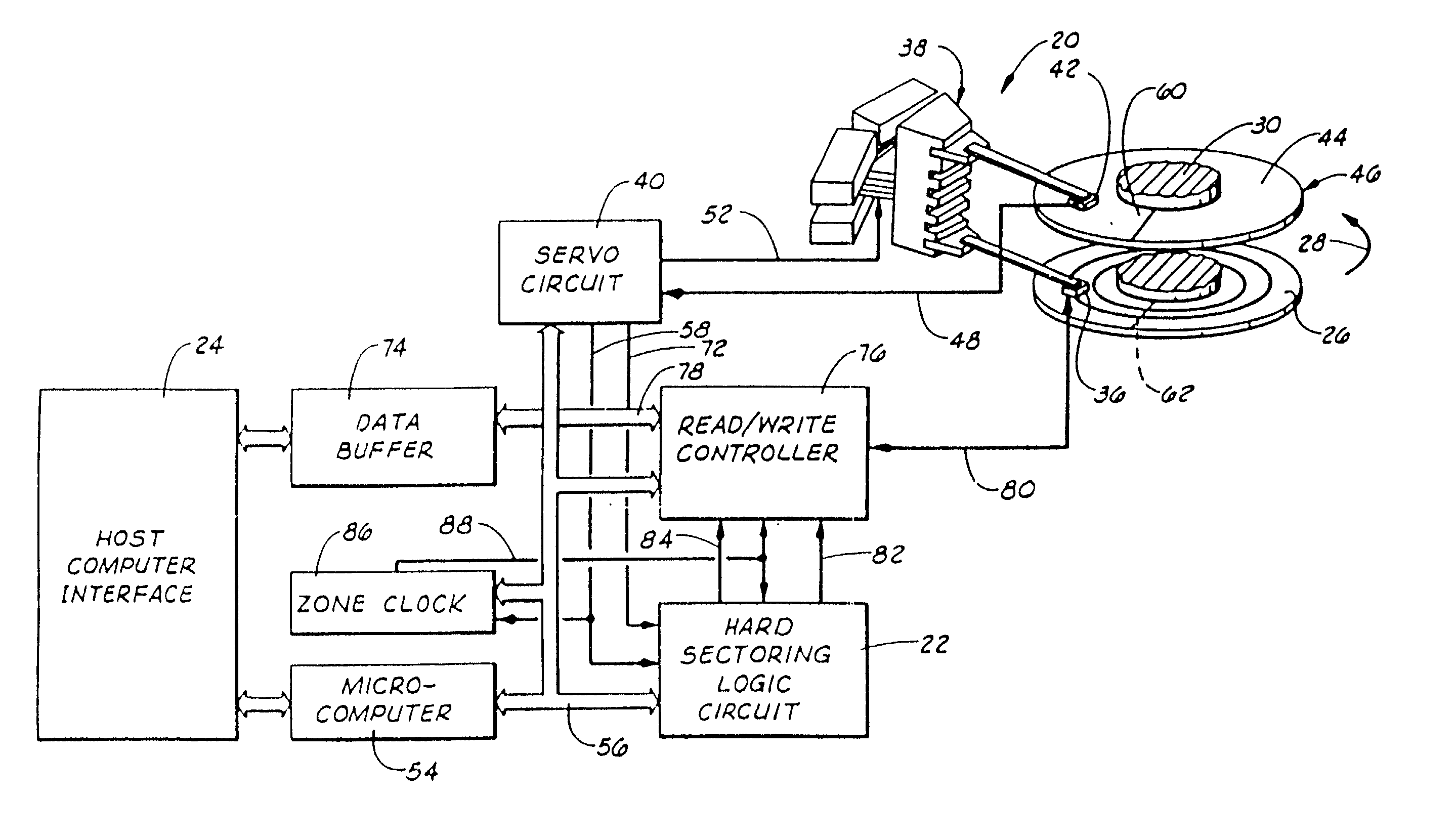
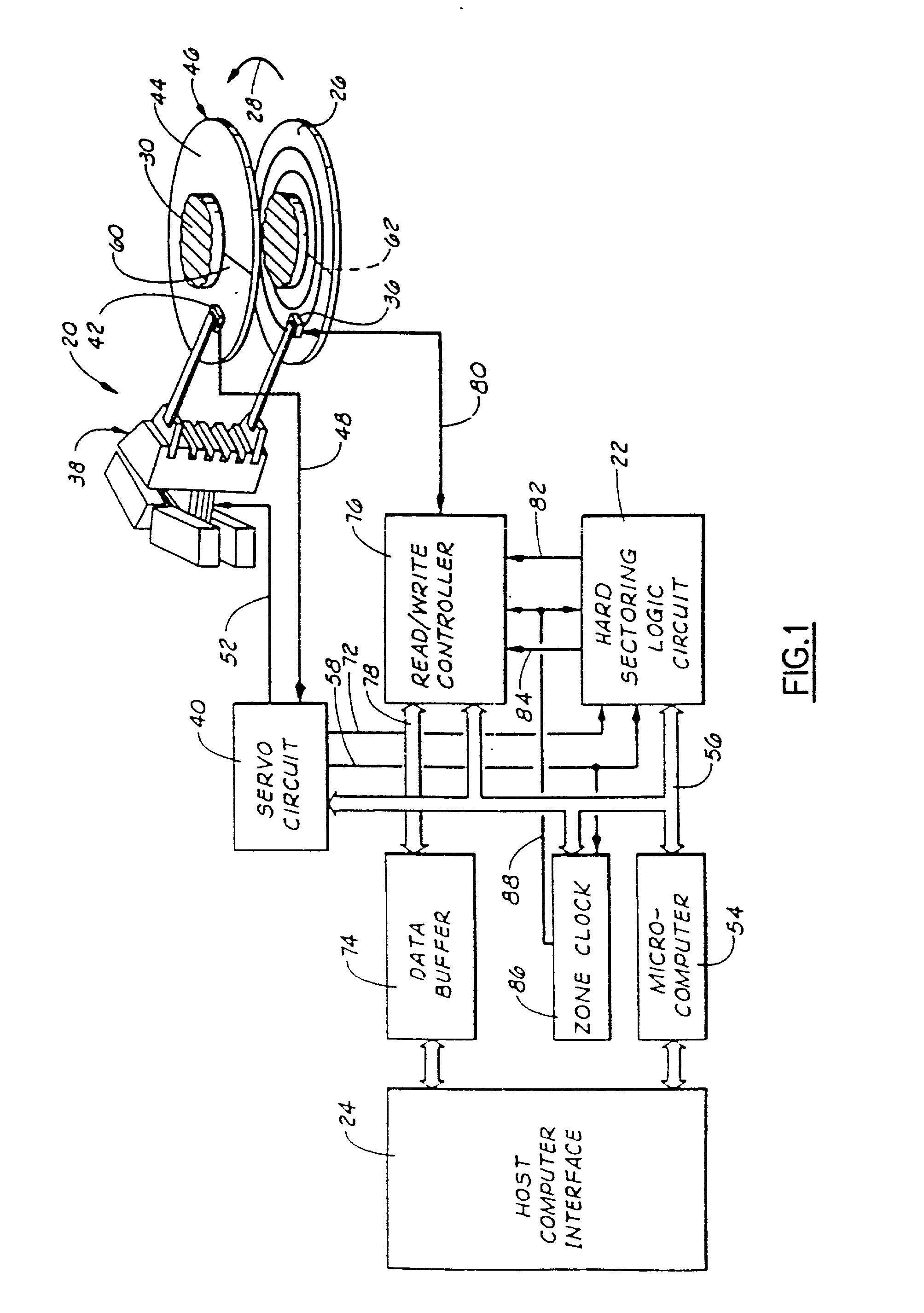
[0050] With this overview, attention is now invited to the components of the circuit 22 which are used in the operation generally described above. Referring first to FIGS. 4 and 5, shown therein respectively are the circuit for the master clock-master reset generator 90 and a timing diagram that illustrates the operation of the generator 90. As shown in FIG. 4, the generator 90 is comprised of a type D master reset flip-flop 157 that receives servo PLO clock signals (shown on time axis 159 in FIG. 5) on path 58 at its clock input and the servo index signal on conducting path 72 at its data input. Additionally, the flip-flop 157 has an active low set input that receives the servo index signal (time axis 161 in FIG. 5) on path 72 via a NOR gate 160. Thus, as the servo index signal, a positive pulse, rises, the output of the NOR gate goes active low to set the flip-flop 157. The master reset pulse on conducting path 92 (time axis 163 in FIG. 5) is delivered from...


PUM

PropertyMeasurementUnit
timeaaaaaaaaaa
disk rotation rateaaaaaaaaaa
lengthaaaaaaaaaa

Abstract

An apparatus for determining a sector location in a disk. A location circuit is configured to determine an angular location of a transducer head according to a selected index location on the disk. A memory is used to store a first value that corresponds to a selected angular distance along a selected track on the disk. An accumulator is configured to add the first value to the value of the content of the accumulator in response to an accumulator clock signal. A comparator is coupled to the location circuit and the accumulator to compare data related to the angular location and the content of the accumulator to generate a result. A generator is coupled to the comparator to provide a sector location signal in response to the result.

Description

[0001] This application is a continuation to U.S. patent application Ser. No. 08 / 116,470, filed Sep. 2, 1993, which is a reissue of U.S. patent application Ser. No. 519,497, filed May 4, 1990, now U.S. Pat. No. 5,050,013, which is a continuation of Ser. No. 445,753, filed Dec. 4, 1989, and now abandoned.[0002] 1. Field of the Invention[0003] The present invention related generally to improvements in rotating disk magnetic data storage devices, and, more particularly, but not by way of limitation to improvements in locating data sectors on the disks of such devices.[0004] 2. Brief Description of the Prior Art[0005] In rotating disk magnetic data storage devices, data is stored in sectors extending angularly along concentric data tracks defined on the disks of the device. The disks have magnetizable surface coatings. Data is written and subsequently read by transducer heads that fly over the surfaces of the disks to magnetize cells of the surface coating, for writing, or respond to di...

Claims


Application Information

Patent Timeline
Patent Type & Authority Applications(United States)
IPC IPC(8): G11B19/02G11B20/12G11B27/10
CPCG11B19/02G11B20/1258G11B2220/2508G11B2020/1282G11B27/10
Inventor HOLSINGER, STEVEN V.
Owner RES INVESTMENT NETWORK
Why Eureka
Try Eureka