
Approach for engine start synchronization

a technology for engine start and synchronization, applied in the direction of engine starters, electric control, instruments, etc., can solve the problems of controller and engine position being out of synchronization, fuel injection control accuracy being reduced, ineffective combustion or no combustion of fuel, etc., to improve engine position confidence, quick and accurate engine startup, and increase the effect of engine position

Inactive Publication Date: 2009-11-19
FORD GLOBAL TECH LLC
View PDF13 Cites 19 Cited by
  • Summary
  • Abstract
  • Description
  • Claims
  • Application Information

AI Technical Summary

Benefits of technology

The patent text describes a method for starting an engine by synchronizing the controller and the engine position based on a correlation between a sensed engine position and a stored engine stop position. This allows for accurate fuel injection control and ensures that the engine is started quickly and synchronized with the controller. The method also addresses the issue of inaccurate identification of the engine position during startup and proposes a solution to improve the accuracy of the engine position for quick and reliable engine startup.

Problems solved by technology

However, the inventor herein has recognized some issues with the above approach.
In particular, in some cases, the first identification of the CID may be inaccurate resulting in the controller and the engine position being out of synchronization.
Moreover, the lack of synchronization may lead to fuel injection control having reduced accuracy.
Lack of synchronization between the controller and the engine position particularly may affect startup of a direct fuel injection engine.
In particular, since fuel is injected directly into the cylinder, if the engine position known by the controller is inaccurate, fuel may be injected into the cylinder at an engine position that is inappropriate for combustion resulting in ineffective combustion or no combustion of the fuel.
Thus, control of fuel injection with reduced accuracy as a result of the controller and the engine position being out of synchronization may result in ineffective combustion or no combustion which may lead to no-starts or miss-starts of the direct fuel injection engine.

Method used


Image

  • Approach for engine start synchronization
  • Approach for engine start synchronization
  • Approach for engine start synchronization

Examples


Embodiment Construction

[0012]The present disclosure is directed to a propulsion system of an automobile. More particularly, the present disclosure is directed to an approach for synchronizing a controller with a position of a direct fuel injection engine of the automobile in order to perform robust startup of the direct injection engine with a reduced likelihood of no-starts or miss-starts.

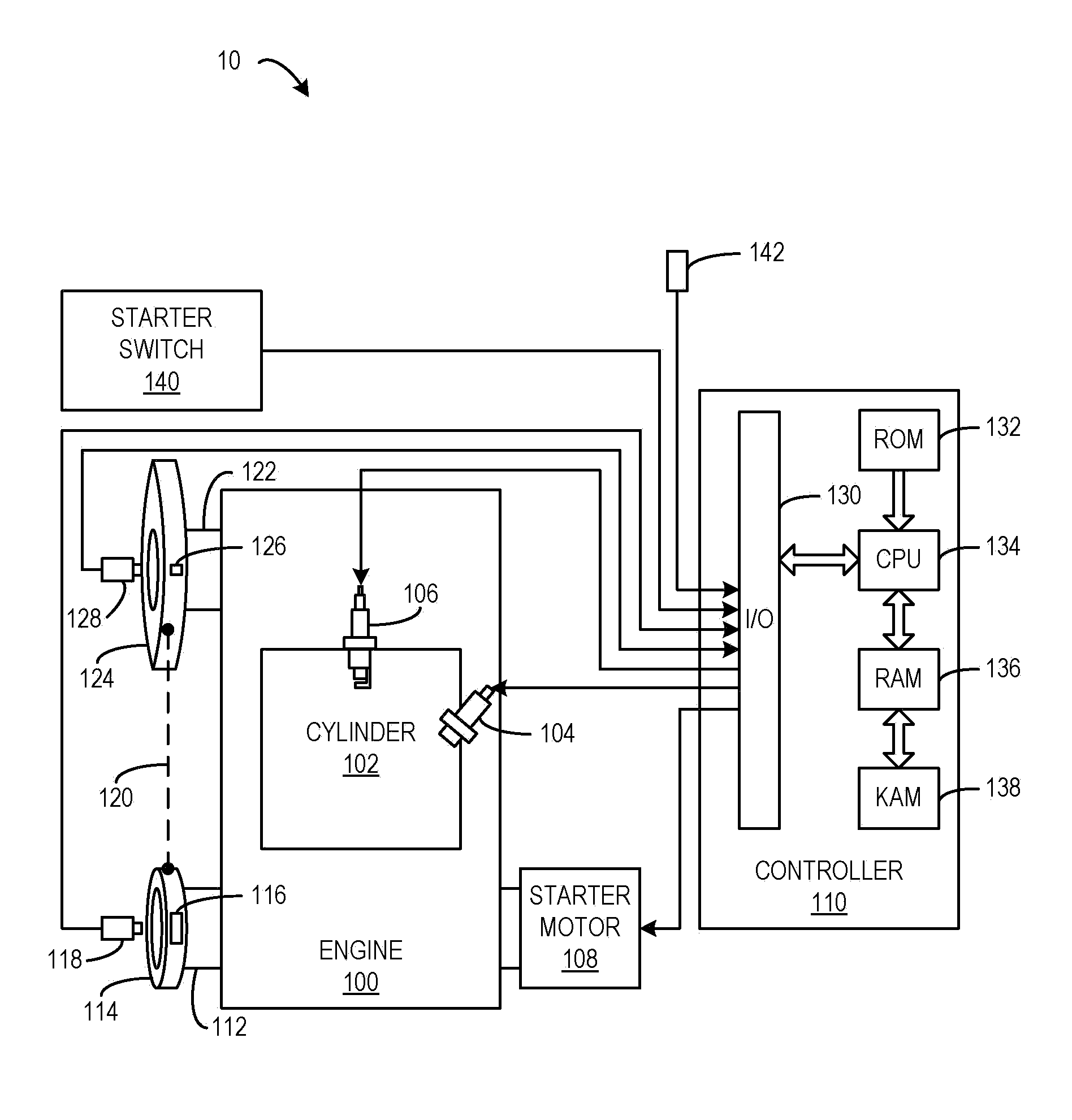
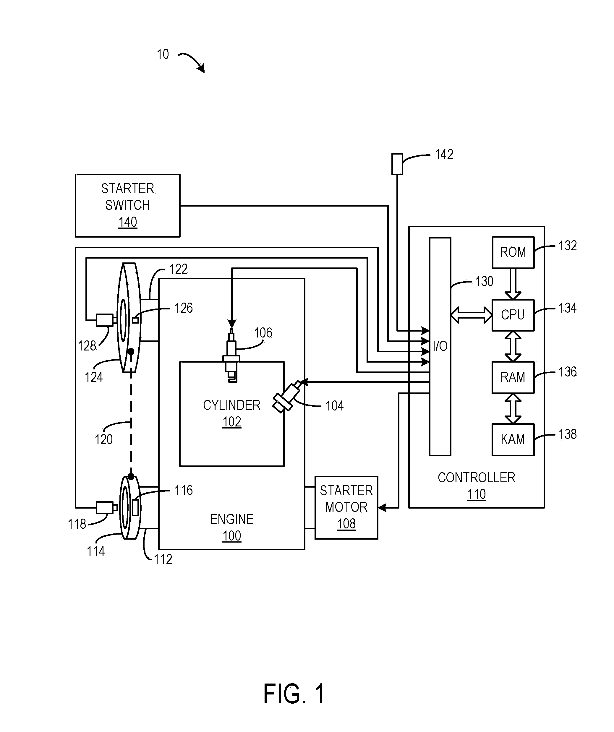
[0013]FIG. 1 is a schematic diagram showing one cylinder 102 of multi-cylinder direct engine 100, which may be included in propulsion system 10 of an automobile. Fuel injector 104 is shown coupled directly to cylinder 102 for injecting fuel directly therein in proportion to a pulse width of a signal received from controller 110. In this manner, fuel injector 104 provides what is known as direct injection of fuel into cylinder 102. The fuel injector may be mounted in the side of the combustion chamber or in the top of the combustion chamber, for example. Fuel may be delivered to fuel injector 104 by a fuel system (not sh...


PUM


Abstract

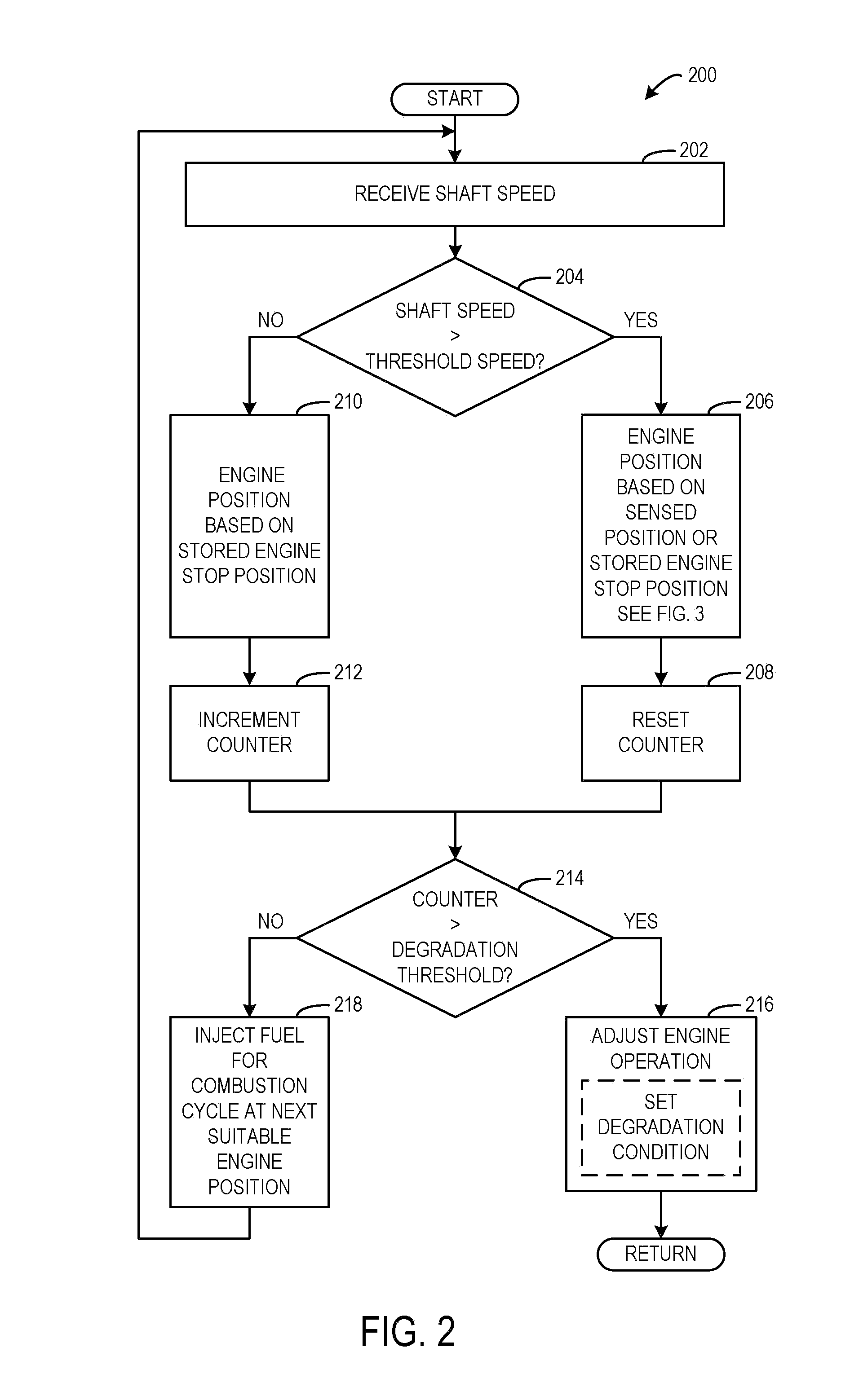
A method of starting an engine is provided. The engine includes a cylinder and a fuel injector configured to directly inject fuel into the cylinder. The method includes: at an engine start condition, receiving a sensed engine position, in response to the sensed engine position correlating with a stored engine stop position, injecting fuel directly into the cylinder at a next suitable engine position for a first combustion cycle, and in response to the sensed engine position not correlating with the stored engine stop position, rotating a shaft of the engine an angular distance without injecting fuel directly into the cylinder until the sensed engine position correlates with another parameter, and thereupon, injecting fuel directly into the cylinder at a next suitable engine position for a first combustion cycle.

Description

BACKGROUND AND SUMMARY [0001]Engine control strategies may control fuel injection for combustion based on engine position. For example, engine position may be determined based on an angular position of one or more shafts of the engine, such as a camshaft or a crankshaft. The angular position of a shaft may be detected by a shaft position sensor configured to send a signal train indicative of position to a controller. In a particular example, an engine may include a fine resolution crankshaft having a crank wheel that includes sixty teeth that generates one hundred twenty edges each revolution. The engine further includes a coarse angular resolution camshaft having five targets that generate ten edges per camshaft revolution. The controller receives signal trains from the sensors based on detection of the teeth of the crankshaft and the targets of the camshaft and the controller time stamps and processes the signals of each signal train to determine the engine position.[0002]At engin...

Claims


Application Information

Patent Timeline
Patent Type & Authority Applications(United States)
IPC IPC(8): F02D45/00
CPCF02D41/009F02D2041/0092F02D41/062
Inventor PURSIFULL, ROSS DYKSTRA
Owner FORD GLOBAL TECH LLC
Learn More