Lateral propulsion unit for aircraft comprising a turbine engine support arch

a technology of turbine engine and support arch, which is applied in the direction of machines/engines, stators, liquid fuel engines, etc., can solve the problems of limiting the possibility of integrating mechanical energy dissipation elements, unable to give optimal distribution of means, and inability of connecting means to resist forces optimally

Active Publication Date: 2014-03-06
AIRBUS OPERATIONS (SAS)
View PDF11 Cites 19 Cited by
  • Summary
  • Abstract
  • Description
  • Claims
  • Application Information

AI Technical Summary

Benefits of technology

[0078]The turbine engine can be dismounted from its service position, and conversely can be connected to the mounting

Problems solved by technology

However, these engine mounting structures do not give an optimum distribution of the means connecting the turbine engine to the rigid structure of these engine mounting structures.
Thus, it is impossible for these connecting means to resist forces optimally.
Furthermore, this type of configuration limits possi

Method used


Image

  • Lateral propulsion unit for aircraft comprising a turbine engine support arch
  • Lateral propulsion unit for aircraft comprising a turbine engine support arch
  • Lateral propulsion unit for aircraft comprising a turbine engine support arch

Examples


Embodiment Construction

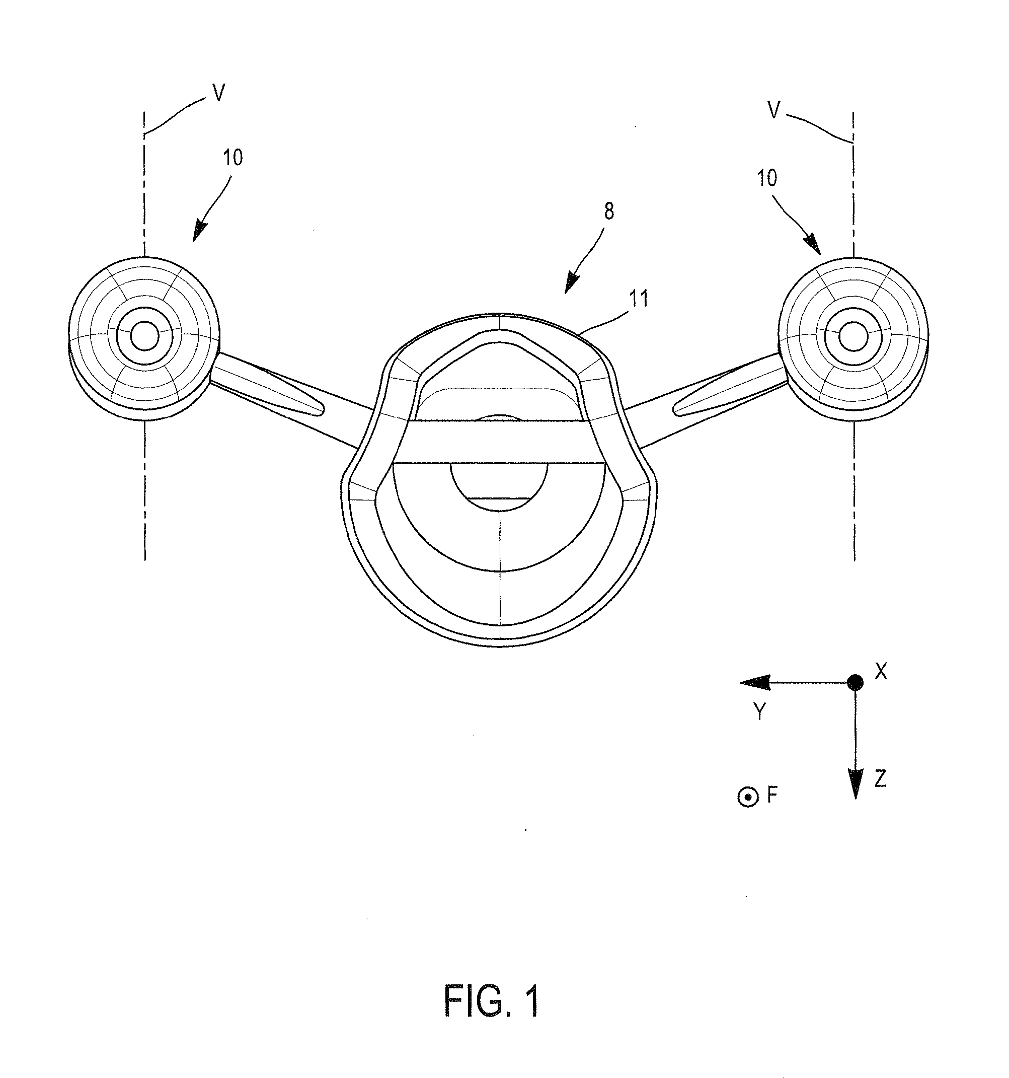
[0101]FIG. 1 very diagrammatically shows an aft part of an aircraft 8 such as a plane seen in a cross-sectional view comprising two propulsion units 10 added laterally on the aircraft fuselage 11. These propulsion units 10 are thus arranged aft from the main wings of the aircraft (not visible in FIG. 1).

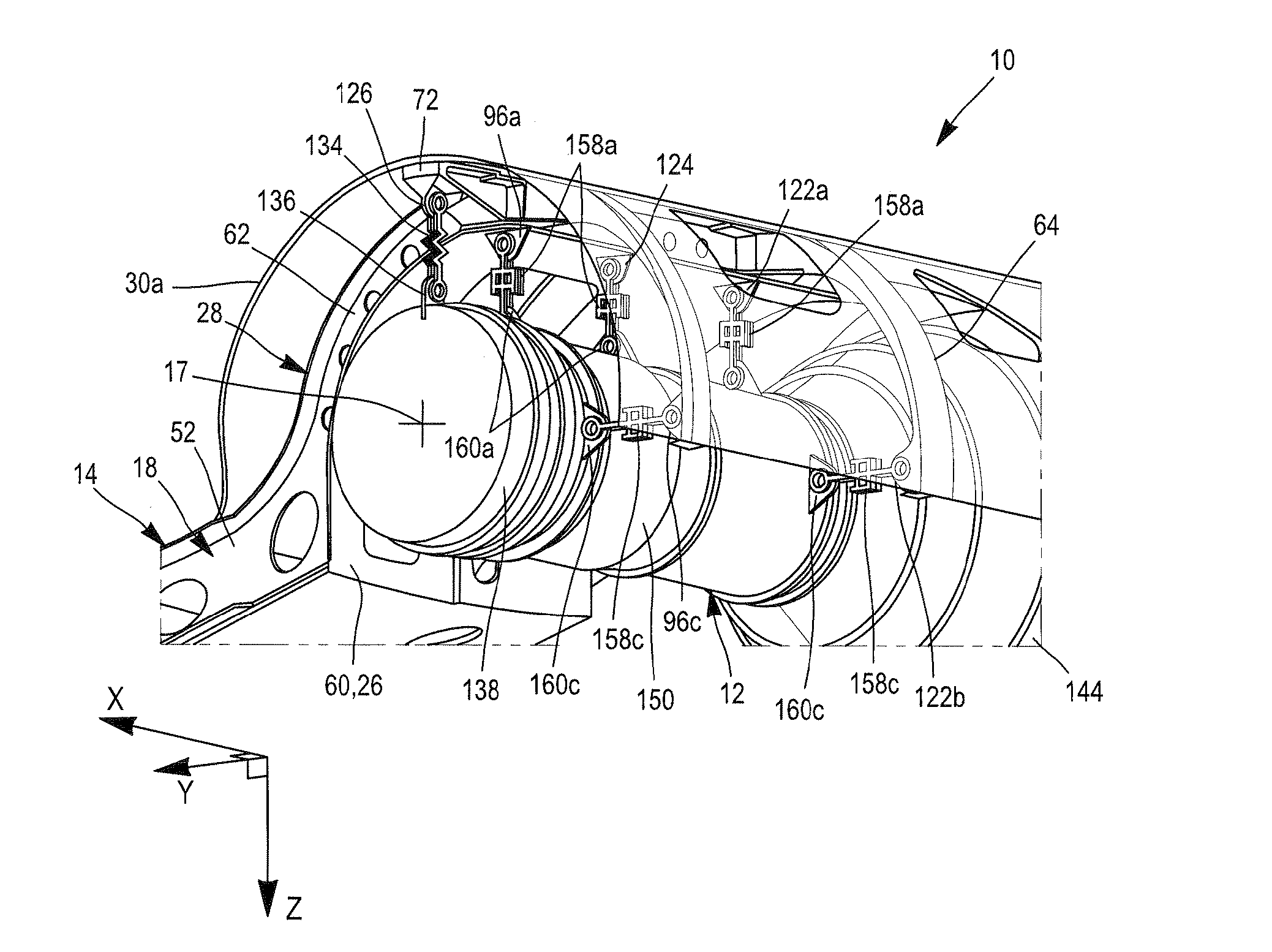
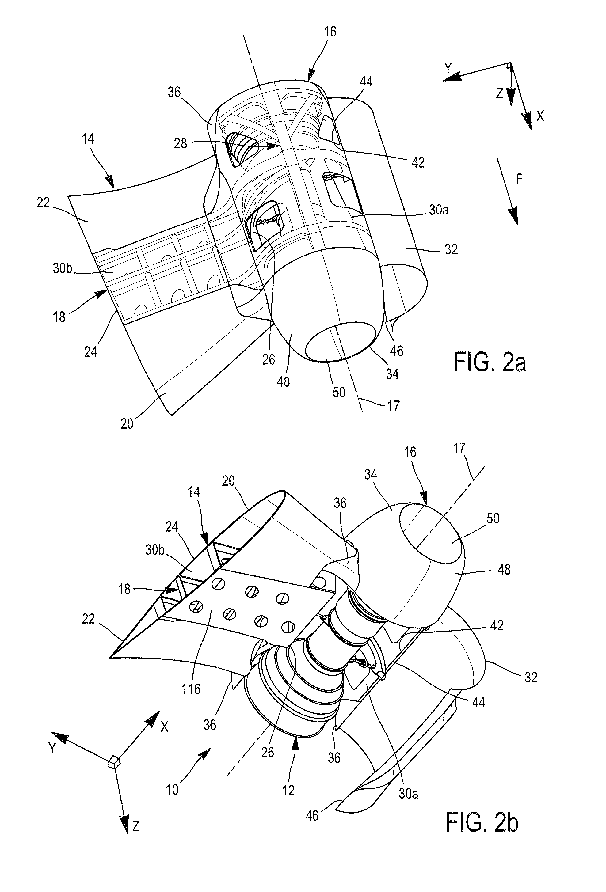
[0102]Each propulsion unit 10 globally comprises a turbine engine 12 (FIG. 2b), a mounting device 14 fixing the turbine engine to an aircraft structure (FIGS. 2a and 2b), and an external aerodynamic fairing 16 that will guide the external airflow, also called the relative wind, around the turbine engine 12.

[0103]In the example shown, the turbine engine 12 is an open rotor pusher type turbojet, with propellers located in an aft part of the turbojet, these propellers not being shown in the figures.

[0104]Throughout the remainder of the description, by convention, X is the longitudinal direction of the turbine engine 12 and more generally of the propulsion unit 10 and the aircraft 8, thi...


PUM


Abstract

A propulsion unit for an aircraft, comprising one turbine engine and a mounting device for a turbine engine designed to be added laterally on an aircraft structure and comprising a rigid mounting structure. The rigid mounting structure supports at least one arch which is concave towards the longitudinal axis of the propulsion unit and which has a distal end at an angular distance of between 45 and 120 degrees from a vertical plane passing through the axis, on the other side of the structure, and supporting a distal connecting element connecting the turbine engine to the arch.

Description

CROSS-REFERENCES TO RELATED APPLICATIONS[0001]This application claims the benefit of the French patent application No. 12 58335 filed on Sep. 6, 2012, the entire disclosures of which are incorporated herein by way of reference.BACKGROUND OF THE INVENTION[0002]This invention relates to the domain of aircraft propulsion units and most particularly concerns means of attaching turbine engines onto the structure of aircraft.[0003]In aircraft, and particularly in planes, conventional turbojets and open rotor turbojets, are usually supported by an engine mounting structure (EMS) comprising a rigid box shaped structure comprising means of connecting the turbojet to this rigid structure. These connecting means are usually distributed into a forward engine mounting and an aft engine mounting globally centered relative to a median plane of the rigid structure, and two thrust resistance rods located on each side of this median plane.[0004]Engine mounting structures of this type are shown in FIG...

Claims


Application Information

Patent Timeline
IPC IPC(8): F01D25/24
CPCF01D25/24B64D27/20B64D27/26B64D29/06Y02T50/40
Inventor BROCHARD, WOLFGANGTERRAL, ROMAIN
Owner AIRBUS OPERATIONS (SAS)
Why Eureka
Try Eureka