Arrangements of base transceiver stations of an area-covering network

Inactive Publication Date: 2002-08-13
LITTLEFEET
View PDF89 Cites 28 Cited by
  • Summary
  • Abstract
  • Description
  • Claims
  • Application Information

AI Technical Summary

Benefits of technology

Independently of the presence of one of more time-lag devices in the transmitting and receiving branch of a base transceiver station, it has proved advantageous if in the receiving branch a device for detecting the field strength of the signal received is provided, which closes a switch incorporated in the transmitting branch if a threshold value is exceeded. This measure makes it possible to actuate in a predetermined manner only the transceiver stations of a cell area in whose cell a mobile station is in fact located, since only here is a radio contact required. By disconnecting the remaining transceiver stations, the overall transmission power being transmitted is reduced, so that common channel interference with the closest cell area sharing the same frequency is significantly reduced.
In this case it is practical if the threshold value is at or slightly below the reception field strength corresponding to

Problems solved by technology

On the other hand, any conventional base transceiver station requires a high level of investment, which considerably increases the cost of the radio network.
It has been proposed in the prior art to provide at each base transceiver station, instead of one non-directional aerial, three directional aerials, each covering a transmission or receptio

Method used


Image

  • Arrangements of base transceiver stations of an area-covering network
  • Arrangements of base transceiver stations of an area-covering network
  • Arrangements of base transceiver stations of an area-covering network

Examples


Embodiment Construction

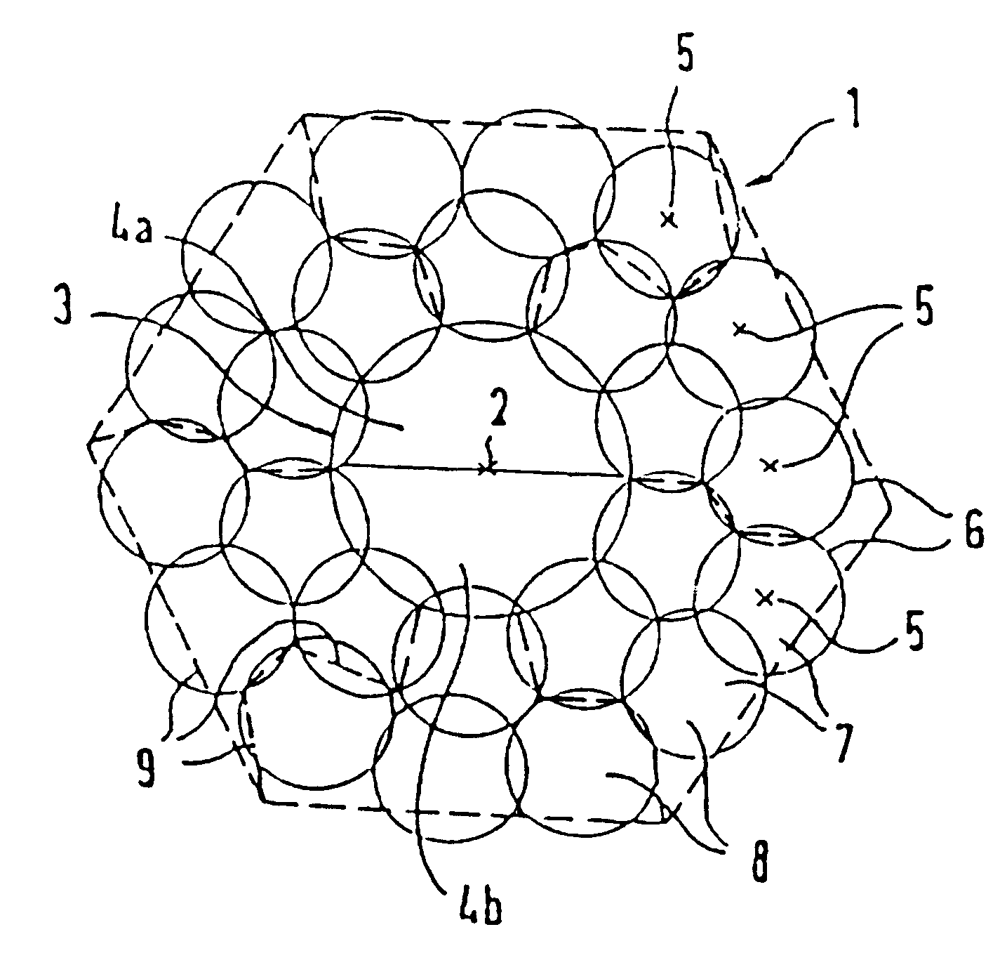
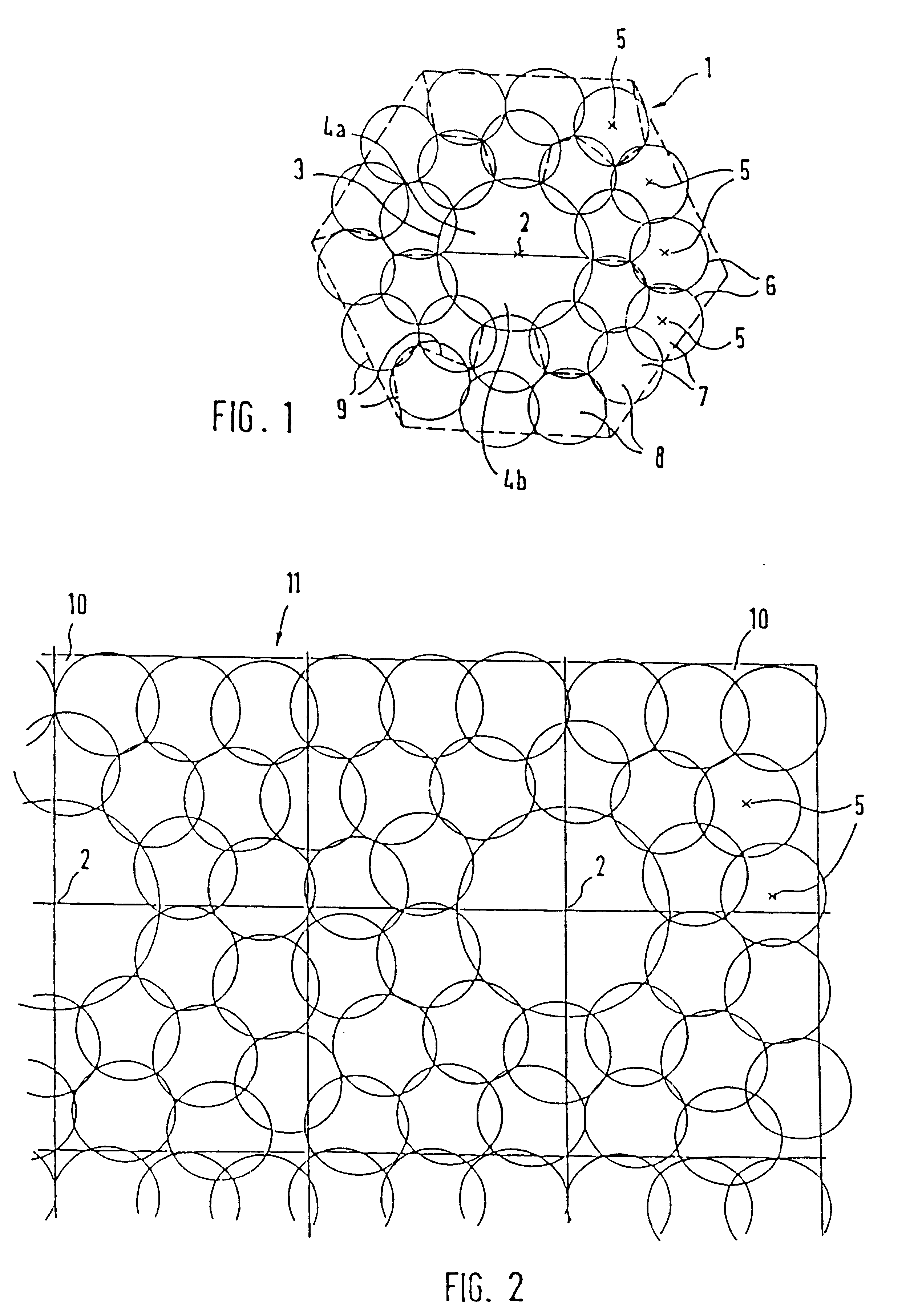
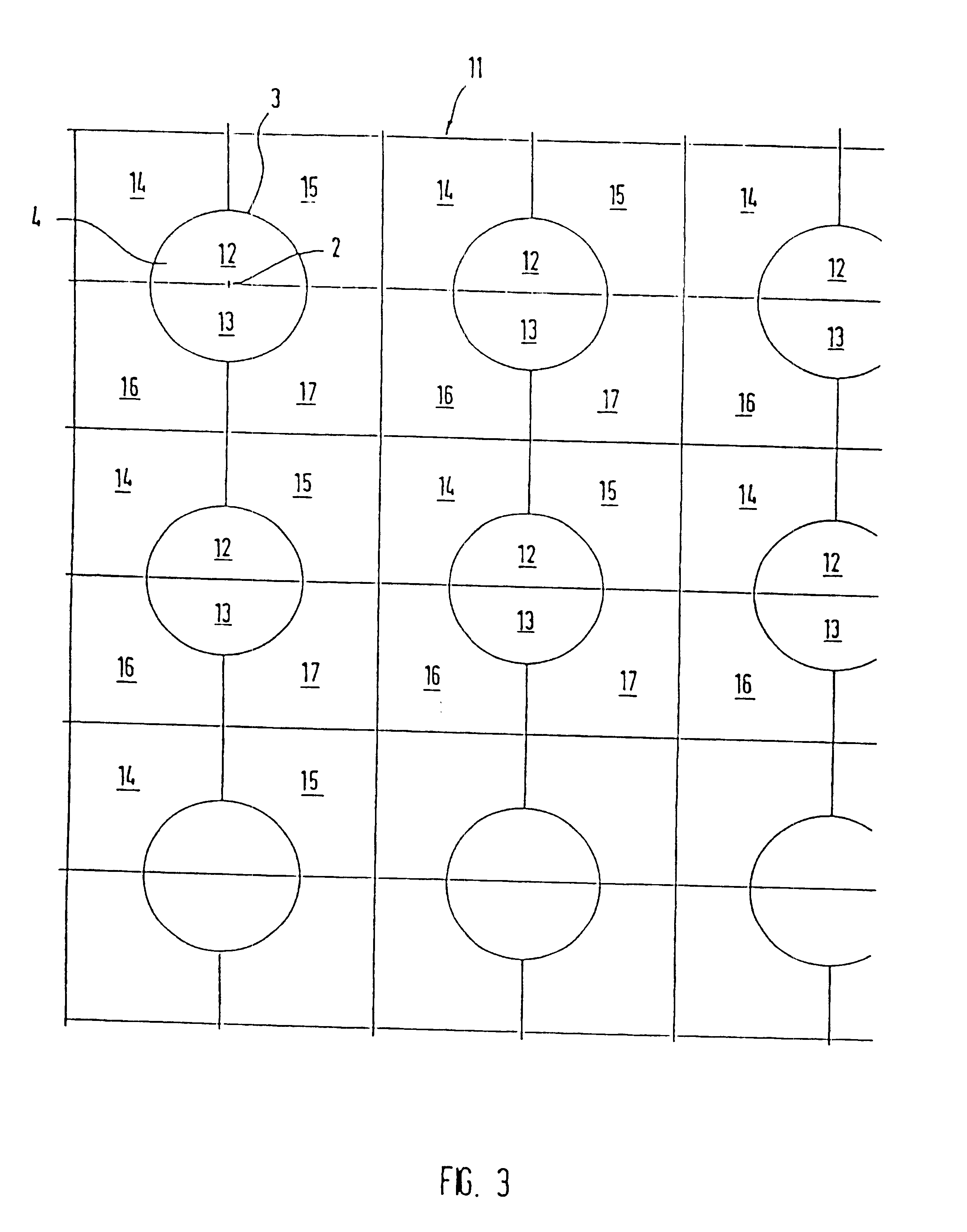
FIG. 1 shows an elementary cell 1, a large number of which can be joined together in lines to form an area-covering radio network having an approximately honeycomb structure. In the centre of the cell 1 is a base transceiver station 2, which is coupled via cable or radio link to a base station controller (not shown). By means of two directional aerials having a range 3, the central transceiver station 2 serves the inner cells 4a and 4b. Within the cells 4a or 4b, a mobile station (not shown) communicates direct with the central transceiver station 2.

In the case shown in FIG. 1, the central transceiver station 2 is surrounded by decentral transceiver stations 5, each having an identical range 6. In the arrangement shown in FIG. 1, the ranges 6 of the decentral radio stations 5 are approximately half as large as the range of the central radio station 2, which is achieved by suitable setting of the levels of transmission power. Thus the ideally circular cells 7 of the decentral transce...


PUM


Abstract

An arrangement of an area covering, cellular radio communication network having cell regions which can be. contiguously replicated without interference. A central transceiver station is coupled to a base station controller and has a plurality of decentral transceiver stations surrounding and coupled to the central transceiver station. Groups of adjacent decentral transceiver stations are grouped in respective cell areas. All of the decentral transceiver stations in each cell area are allocated the same transmission frequencies, but the frequencies of each cell area are different from the other cell areas in the cell region.

Description

FIELD OF THE INVENTIONThe invention relates to a plurality of arrangements of base transceiver stations of an area-covering radio network and to a method of operating such an arrangement.The invention further comprises base transceiver stations adapted to the new arrangements and a method of subsequently compressing an existing continuous radio network.DESCRIPTION OF RELATED ARTIn order to operate radio telephones, in addition to the respective mobile stations, an area-covering network of fixed transmission stations is necessary in order to ensure interference-free radio operation at any location within the area of coverage.In order to permit a large number of mutually independent radio participants to use their telephones simultaneously, the region of coverage is divided into a plurality of individual cells, each allocated with its own base transceiver station. By giving adjacent zones different frequencies, it is possible to identify a particular radio telephone with a respective ...

Claims


Application Information

Patent Timeline
IPC IPC(8): H04B7/26H04Q7/36H04W16/02H04W16/12H04W16/24H04W16/26
CPCH04B7/2609H04W16/02H04W16/12H04W16/24H04W16/26
Inventor SCHEINERT, STEFAN
Owner LITTLEFEET
Why Eureka
Try Eureka