Electromotive chain saw

a technology of electromagnetism and chain saw, which is applied in the direction of motor/generator/converter stopper, dynamo-electric converter control, metal sawing accessories, etc., can solve the problems of inability to go to the subsequent steps of work, inadvertent damage to material in process, and rotation of cutting chain for several seconds, so as to improve the durability of the clutch mechanism and enhance the durability of the engagement detent and other clutch components.

Inactive Publication Date: 2002-09-10
MAKITA CORP
View PDF70 Cites 18 Cited by
  • Summary
  • Abstract
  • Description
  • Claims
  • Application Information

AI Technical Summary

Benefits of technology

In addition, a further advantage of the present invention is provided by the provision of the aforementioned dynamic braking. In actual operation of the conventional electromotive chain saw, when the released trigger member is turned on immediately after turning off, if the motor is still inertial rotated, the rotating clutch components are going to be engaged with one another and the rotary drive force of the electric motor is applied to an engagement detent and other components, thereby impairing the durability of the clutch mechanism. However, in the present invention, the electric motor is also stopped by the dynamic braking. Therefore, the durability of the engagement detent and other clutch components is enhanced.
In the electromotive chain saw, a conventional brake band can be wound around the brake drum, and a trigger link mechanical brake can be provided. By operating a hand guard and pulling the connected end of the brake band, the brake drum is tightened with the brake band, thereby stopping the cutting chain against the rotary drive force of the electric motor. Also, by releasing the trigger member, the cutting chain is stopped directly by the trigger link mechanical brake and indirectly by the trigger link brake circuit.
The trigger link mechanical brake of the electromotive chain saw is provided with an operable member secured to an end of the brake band, for cooperating with the trigger member, such that the brake band is pull

Problems solved by technology

However, in such electromotive chain saws, even after a trigger member is released and a motor drive switch is turned off, the inertial rotation of the motor often results in the rotation of the cutting chain for several seconds.
If the rotating chain contacts or hits the ground, it is often damaged, thereby requiring the replacement of the chain itself.
The material in proc

Method used


Image

  • Electromotive chain saw
  • Electromotive chain saw
  • Electromotive chain saw

Examples


first embodiment

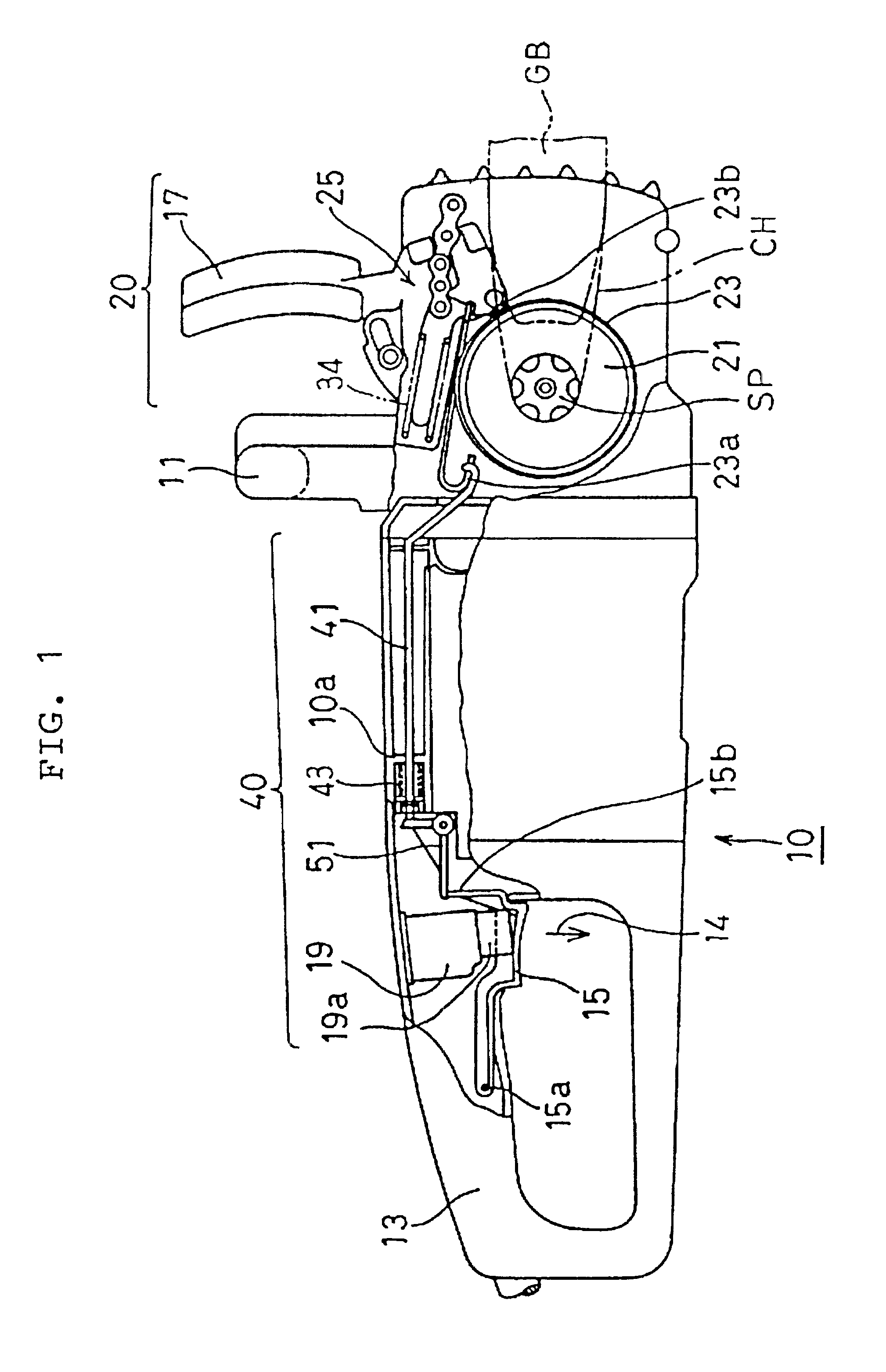
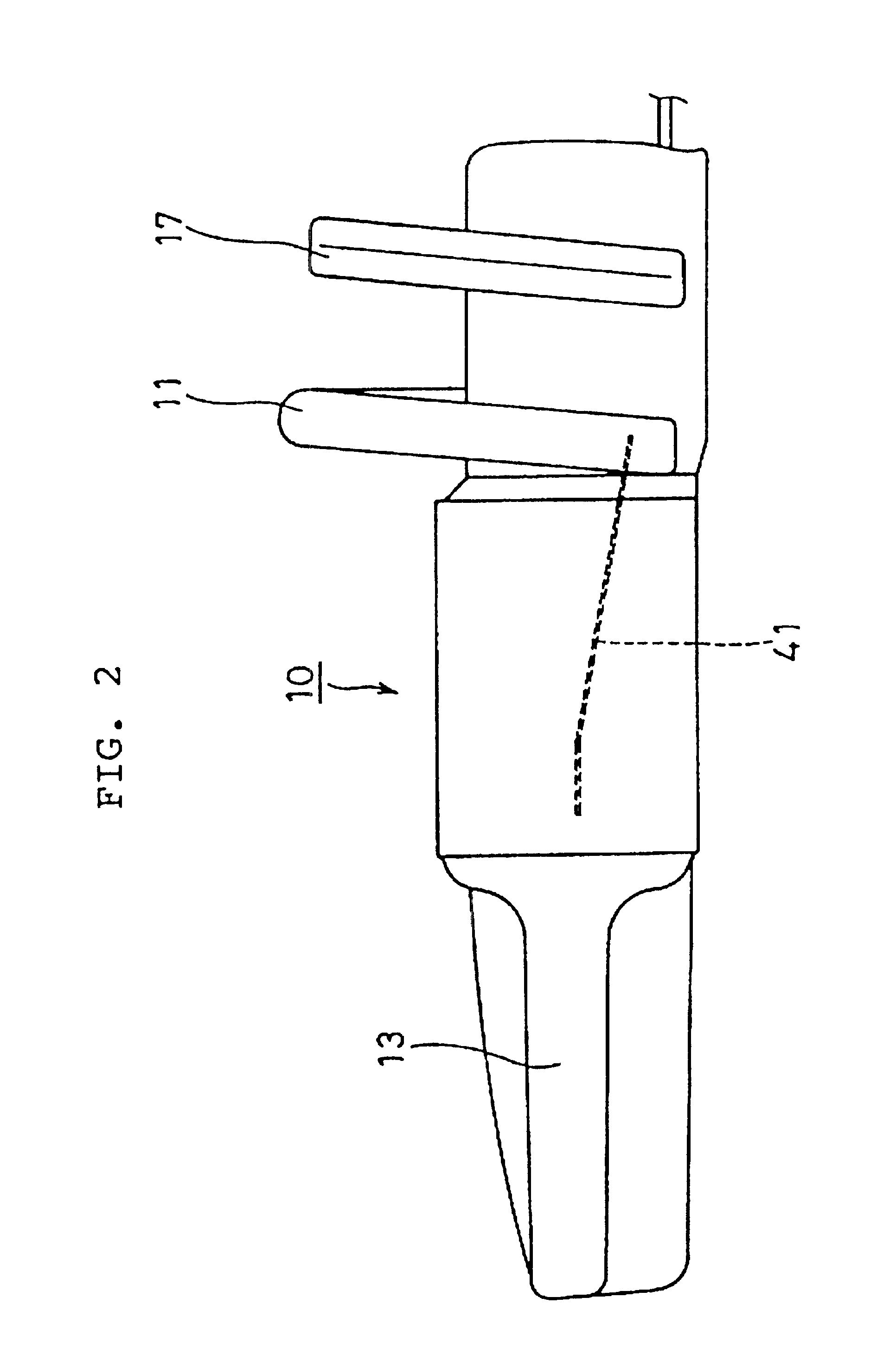
As shown in FIG. 1, in an electromotive chain saw 10 of the first embodiment, a chain CH is wound around a guide bar GB extending from a housing and is driven with an electric motor M (as shown in FIG. 8) and a not-shown centrifugal clutch built into the housing. The electromotive chain saw 10 is manually held with a forward handle 11 and a rearward handle 13. The grip of the rearward handle 13 is provided with a movable trigger lever 15. A hand guard 17 is disposed in front of the forward handle 11, with a hand guard brake device 20 built therein, which is operated by turning the hand guard 17 in the direction shown by arrow 16 in FIG. 3. The trigger lever 15 is normally urged, by a spring having a switch built therein, in the direction shown by an arrow 14 in FIG. 1, and is brought in contact with a push button 19a of a power switch 19 of the electric motor when depressed.

As shown in FIG. 3, the hand guard the brake device 20 applied in cooperation with the hand guard 17 is formed...

second embodiment

A second embodiment is now explained. The second embodiment is the same as the first embodiment in that the brake circuit 62 for dynamic braking as shown in FIG. 4, the hand guard brake device 20 operatively connected to the hand guard 17, and the centrifugal clutch are provided. The components having the same reference numerals as those of the components of the first embodiment are not explained hereinafter. only the aspect of the second embodiment different from the first embodiment, the structure of the mechanical brake device operated when the trigger lever is let off, is explained.

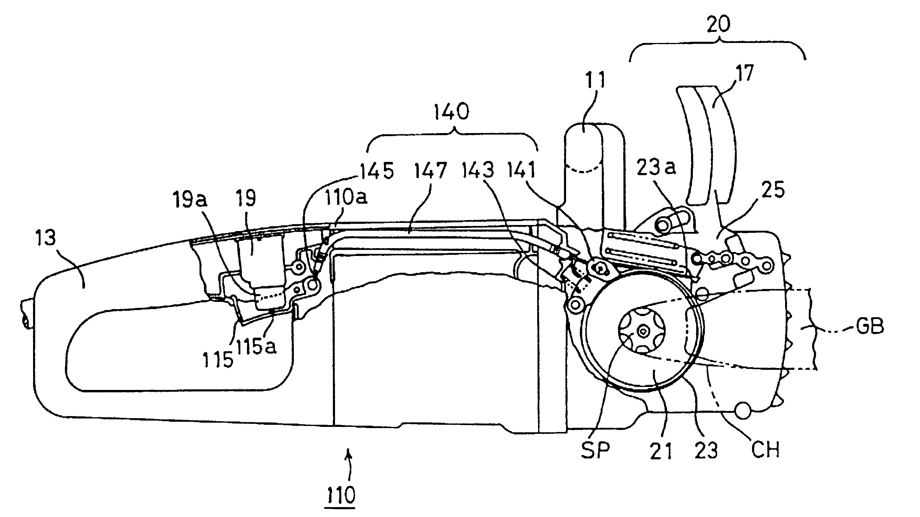
In a chain saw 110 according to the second embodiment, as shown in FIGS. 5 and 6, a mechanical brake device 140 is composed of a brake shoe 141 which can be swung on a support 142a and can be engaged with the periphery of brake drum 21. The mechanical brake device 140 is also composed of a coil spring 143 for urging the brake shoe 141 to engage with the brake drum 21, and a wire 145 connected at one e...

third embodiment

A third embodiment is now explained referring to FIGS. 8-12. The third embodiment is the same as the first embodiment in that the electric drive and brake device 60 for dynamic braking as shown in FIG. 4, and the hand guard brake device 20 operatively connected to the hand guard 17 are provided. The components having the same reference numerals as those of the components of the first embodiment are not explained hereinafter. The aspects of the third embodiment different from the first embodiment, the clutch mechanism, the mechanical brake device operated when the trigger lever is released and the circuit structure of the electric drive and brake device, are explained.

In an electromotive chain saw 560 according to the third embodiment shown in FIG. 8, a trigger-linked mechanical brake 570 is driven with a linkage when a trigger member 585 is released, thereby disconnecting a clutch 590 and stopping the brake drum 521. The hand gaurd brake device, operated by turning the hand guard 17...


PUM

PropertyMeasurementUnit
Forceaaaaaaaaaa
Sizeaaaaaaaaaa
Speedaaaaaaaaaa

Abstract

The chain of an electromotive chain saw is quickly stopped by the combined use of an electric brake and a mechanical brake when a trigger member is turned off. The rear end of a brake band disposed to tighten a brake drum by operating a hand guard is secured to a bent rod. When the trigger member is released, the brake band is normally tightened around the outer periphery of a brake drum by the urging force of a coil spring. When the trigger member is released, a circuit provided with a brake winding is closed, thereby applying a dynamic braking force. When the dynamic brake force is applied, a centrifugal clutch is released quickly and the speed of stopping the brake drum is accelerated.

Description

FIELD OF THE INVENTIONThis invention relates to an electromotive chain saw.BACKGROUND OF THE INVENTIONIn a conventional electromotive chain saw, a hand guard for protecting an operator's hands is provided in front of a handle. Additionally, a brake band is wound around a brake drum for stopping the operation of a cutting chain. By operating the hand guard and pulling one end of the brake band, the brake drum is tightened with the brake band, thereby stopping the cutting chain.However, in such electromotive chain saws, even after a trigger member is released and a motor drive switch is turned off, the inertial rotation of the motor often results in the rotation of the cutting chain for several seconds. If the rotating chain contacts or hits the ground, it is often damaged, thereby requiring the replacement of the chain itself. The material in process is also inadvertently damaged. Furthermore, the operator cannot go to the subsequent steps of work until the chain is completely stoppe...

Claims


Application Information

Patent Timeline
IPC IPC(8): B27B17/00B27B17/08H02P3/00H02P3/04B23D57/02B27G19/06
CPCB27B17/083H02P3/04Y10S83/01
Inventor NAKAMURA, KAZUYAMIZUTANI, MAKOTOKONDO, MASAKI
Owner MAKITA CORP
Why Eureka
Try Eureka