

Valve with outlet flow rate regulation, and container equipped with such a valve
- Summary
- Abstract
- Description
- Claims
- Application Information
AI Technical Summary
Benefits of technology
Problems solved by technology
Method used
Image

Examples
Embodiment Construction
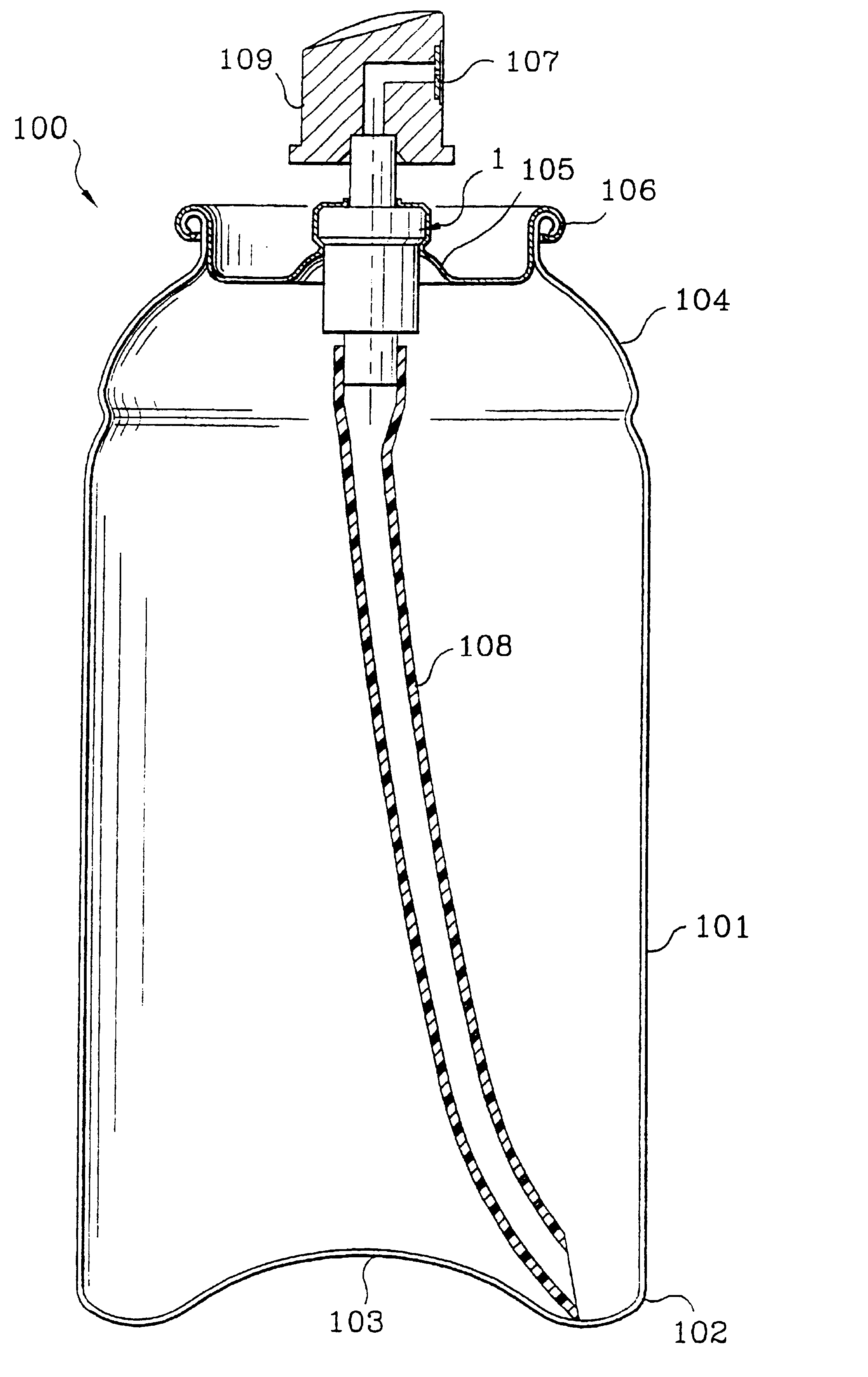
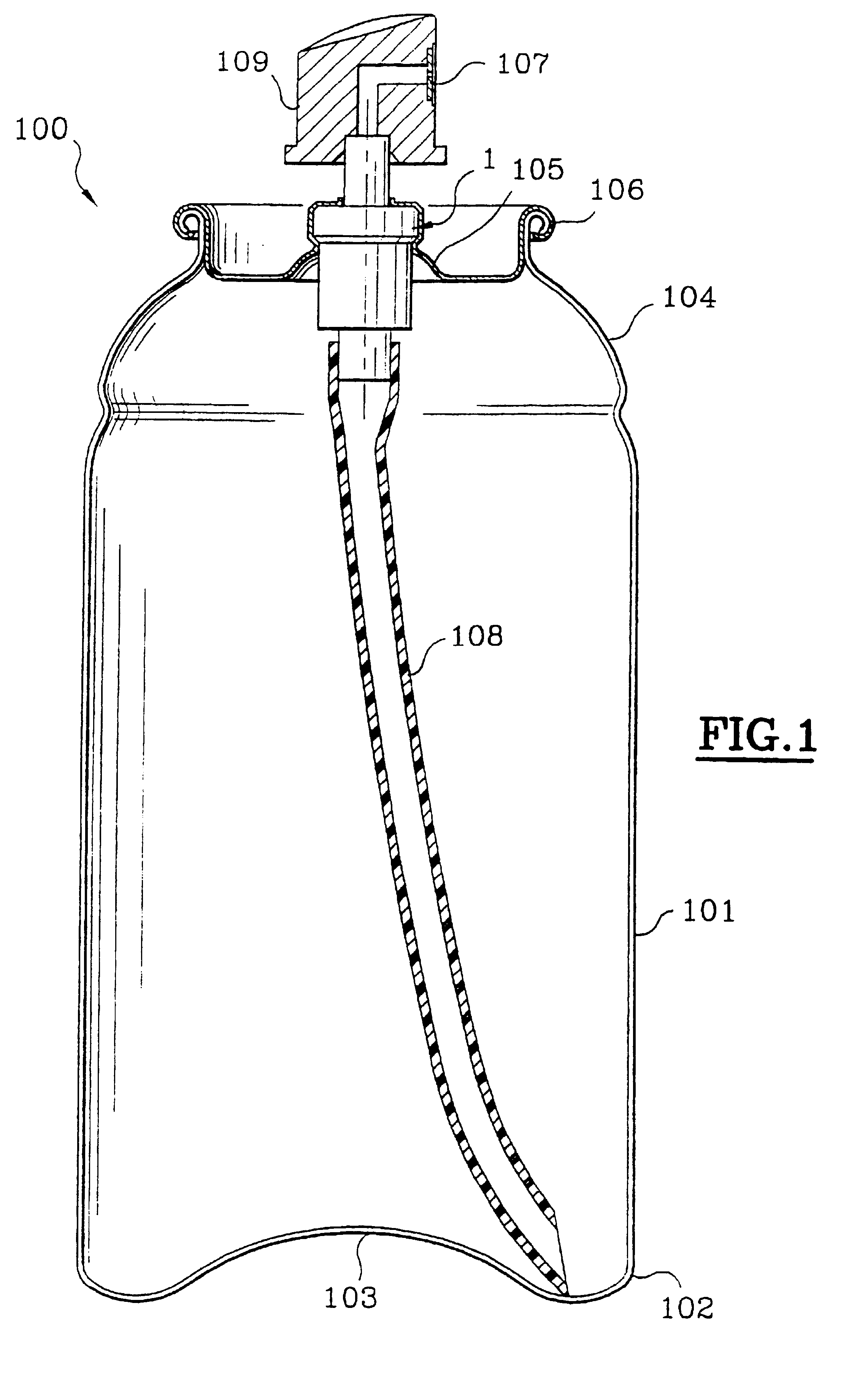
The container 100 depicted in FIG. 1 is in the form of a can, for example made of aluminium, comprising a body 101, and a first end 102 which is closed by an end wall 103. A second end 104 is open and is surmounted by a valve 1 mounted on a dish 105, crimped to a rolled-over edge 106 of the can. The valve 1 is crimped or clipped to the dish 105. A push-button 109 is mounted on the valve so as to allow the valve 1 to be actuated and the product to be diffused via an outlet nozzle 107. A dip tube 108 is connected to the valve 1 and descends more or less as far as the end wall 103 of the can. The valve will be described in detail with reference to FIGS. 2A-2C and 3A-3C.
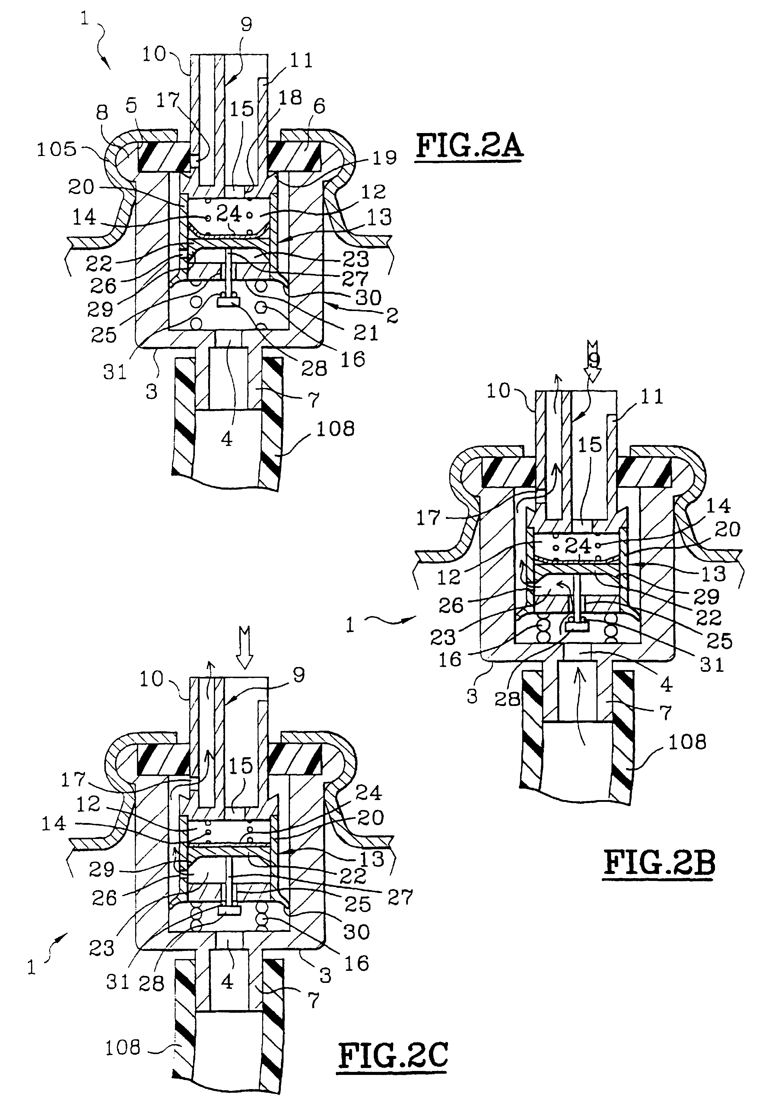
In the embodiment of FIGS. 2A-2C, the valve 1 mainly comprises a body 2, the end wall 3 of which has, at its center, an orifice 4 surrounded by an axial hollow shaft 7, arranged outside the valve body 2, and intended to receive a dip tube 108. The end of the valve body opposite to the end wall 3 is open. The edge delimit...
PUM
 Abstract
Description
Claims
Application Information