Eureka AIR delivers breakthrough ideas for toughest innovation challenges, trusted by R&D personnel around the world.

Variable transfer rate control coding apparatus, reproducing apparatus and recording medium

Inactive Publication Date: 2003-08-19
JVC KENWOOD CORP A CORP OF JAPAN
View PDF20 Cites 8 Cited by
  • Summary
  • Abstract
  • Description
  • Claims
  • Application Information

AI Technical Summary

Benefits of technology

Further, the target rate setting means of a preferred embodiment (namely, a variable transfer rate control coding apparatus) of the present invention is provided with a transfer rate converting device which converts the temporary transfer rate corresponding to each unit period of time into the target transfer rate corresponding to each unit period of time by making increase in the target transfer rate be less than increase in the corresponding temporary transfer rate and limiting the maximum value of the target transfer rate to a predetermined constant value.
As stated above, the variable transfer rate information reproducing apparatus and the recording medium used therein of the present invention have excellent effects in practical use.

Problems solved by technology

This is due to the fact that in case of a block having large activity, change in image signal is large and that an error is not noticeable and that in contrast, in case of a block having small activity, even a small error is conspicuous.
Incidentally, when using DCT or the like, a quantization error is conspicuous in a block of an edge portion.
Thus, the conventional coding apparatus has a drawback in that although an amount of codes corresponding to a portion of an image is sufficient and a corresponding quantization step width is too narrow, an amount of codes corresponding to another portion of the image is insufficient and a corresponding quantization step width is large (namely, quantization is coarse) and thus the picture quality is degraded.
Thus, the conventional coding apparatus has another drawback in that if the length of a moving picture is shorter than the maximum recordable time of a recording medium to be used to record the moving picture, a part of the recordable area of the recording medium remains unused.
However, in case of the conventional coding apparatus, it is not possible that the relative speed between a recording medium and a reproducing head is changed frequency and quickly according to the transfer rate for transferring the variable transfer rate information.
Therefore, the prior art has a drawback in that variable transfer rate information can not be reproduced from a recording medium on which the variable transfer rate information is recorded by changing the transfer rate each predetermined period of time.

Method used


Image

  • Variable transfer rate control coding apparatus, reproducing apparatus and recording medium
  • Variable transfer rate control coding apparatus, reproducing apparatus and recording medium
  • Variable transfer rate control coding apparatus, reproducing apparatus and recording medium

Examples


Embodiment Construction

Hereinafter, preferred embodiments of the present invention will be described in detail by referring to the accompanying drawings.

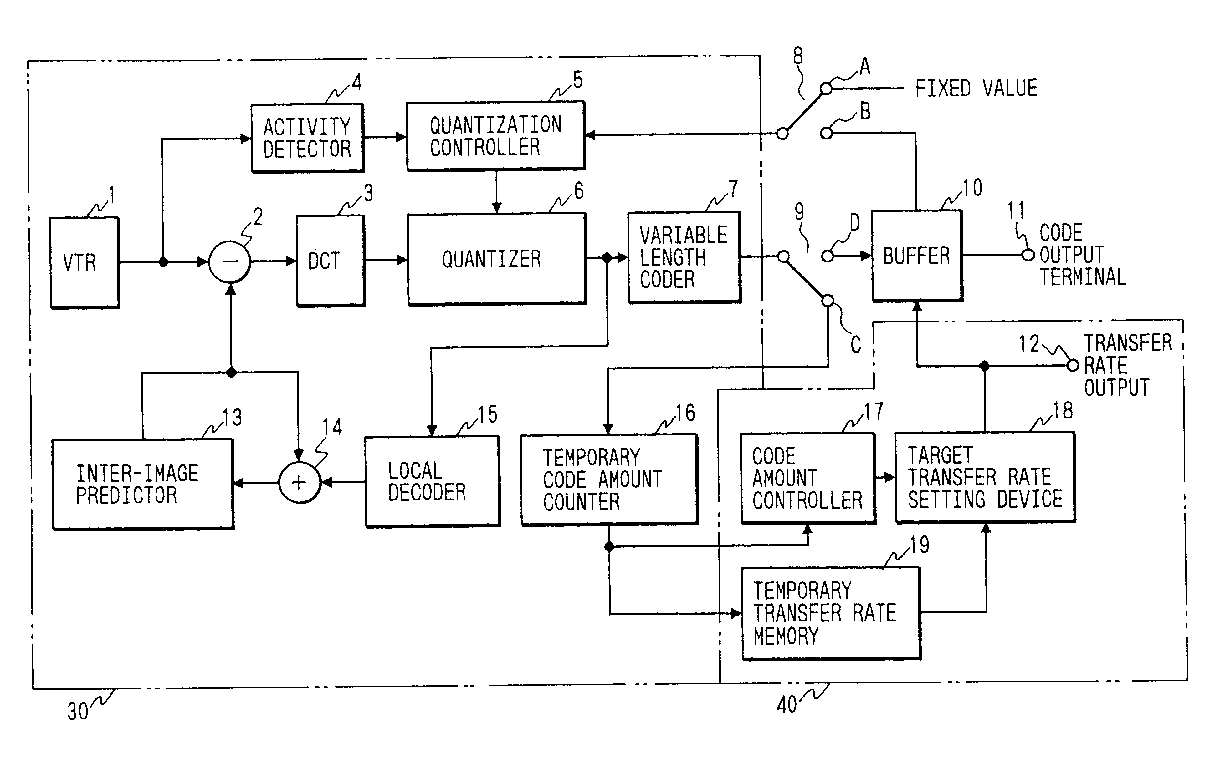
FIG. 4 is a schematic block diagram for illustrating the configuration of a variable transfer rate control coding apparatus embodying the present invention.

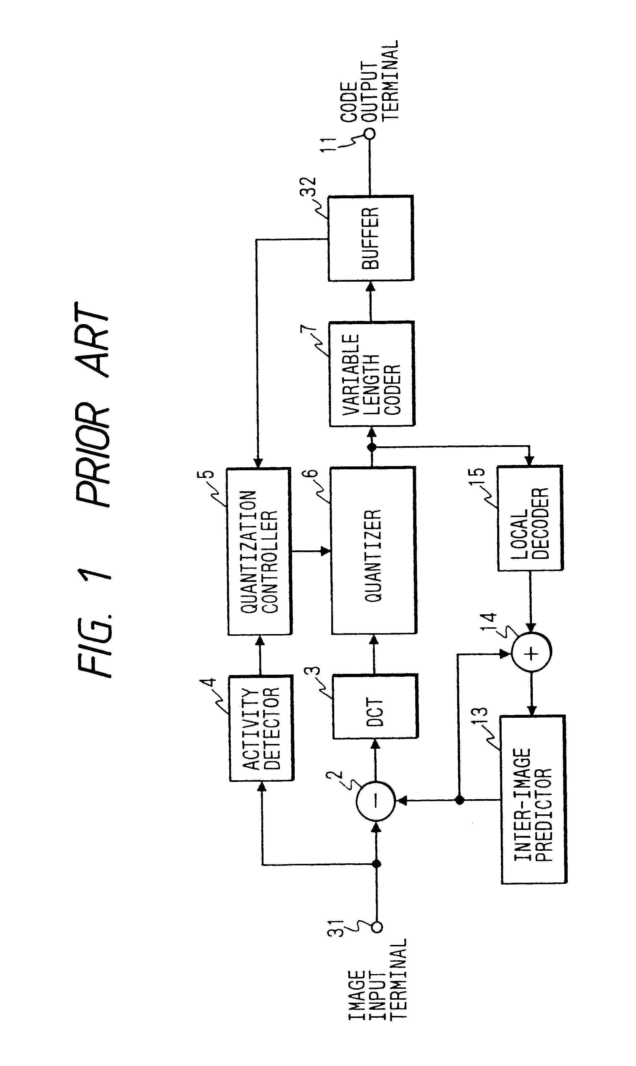
In this figure, like reference characters designate like or corresponding parts of the conventional apparatus of FIG. 1.

Principal differences between the coding apparatuses of FIGS. 1 and 4 (namely, composing elements of FIG. 4 which are not contained in FIG. 1) are a VTR 1, selectors 8 and 9, a temporary code amount counter 16, a code amount controller 17, a target transfer rate setting device 18 and a temporary transfer rate memory 19.

Hereinafter, a coding performed in this variable transfer rate control coding apparatus will be described in detail by referring to FIG. 4.

A coding is performed on a same moving picture signal two times. At first time, a coding process is performed for effecting a tempo...


PUM


Abstract

A variable transfer rate control coding apparatus which can distribute codes of an amount most suitable to the contents of a moving picture to be recorded and to a recording medium, on which information is recorded by this transfer rate coding apparatus, by obtaining an amount of codes to be temporarily generated in each unit period of time by a temporary or tentative coding, and then storing a temporary transfer rate (namely, a value of the temporary amount of codes to be generated in each unit period of time), and setting a target transfer rate (namely, a target value of an amount) of codes to be sent in each unit period of time from a total of the temporary transfer rates and the recordable capacity of the recording medium and next performing an actual or real coding according to the target transfer rates.

Description

BACKGROUND OF THE INVENTION1. Field of The InventionThis invention generally relates to a highly-efficient encoding technique to be employed for efficiently performing a coding (or encoding) in digital-signal recording, transmission and display apparatuses to generate a smaller amount of codes (hereunder sometimes referred to simply as code amount). More particularly, this invention relates to a coding apparatus adapted to perform a coding of a moving picture signal by controlling a transfer rate and also relates to a recording medium on which a code generated by the coding apparatus is recorded. Further, this invention relates to a reproducing apparatus for reading moving picture information from the recording medium. More particularly, this invention relates to a variable transfer rate recording information reproducing apparatus for reproducing moving picture information recorded on a recording medium, which information represents a code generated by changing an amount of informat...

Claims


Application Information

Patent Timeline
IPC IPC(8): H04N7/50H04N7/24H04N7/52H04N7/54H04N5/926H04N21/234H04N21/2368H04N21/434H04N21/44
CPCH04N5/9264H04N7/54H04N19/172H04N19/15H04N19/115H04N19/61H04N19/124H04N19/14H04N19/146H04N19/152G11B20/10527
Inventor SUGIYAMA, KENJIKAYANUMA, KANJIANDO, ICHIRO
Owner JVC KENWOOD CORP A CORP OF JAPAN
Why Eureka
Eureka Blog
Learn More