
Continuous chain caster and method

a technology which is applied in the field of continuous chain caster and caster body, can solve the problems of surface and shape problems, affecting the cooling effect, so as to prevent undesirable deformation, enhance cooling effect, and abnormal microstructure

Inactive Publication Date: 2004-07-13
HUNTER DOUGLAS IND BV
View PDF20 Cites 6 Cited by
  • Summary
  • Abstract
  • Description
  • Claims
  • Application Information

AI Technical Summary

Benefits of technology

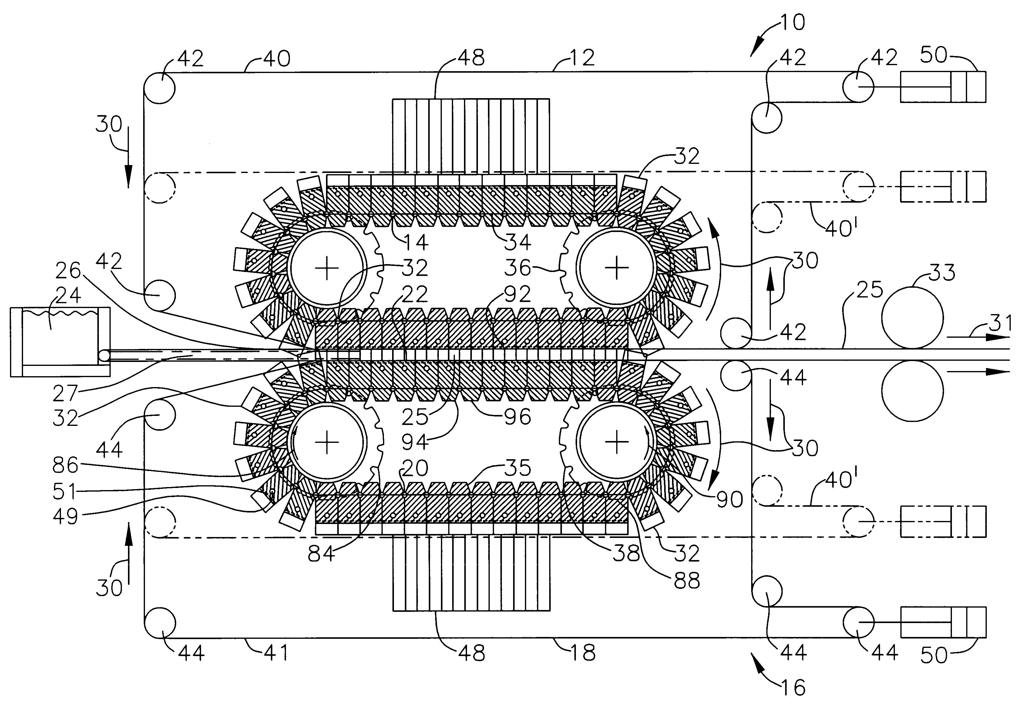
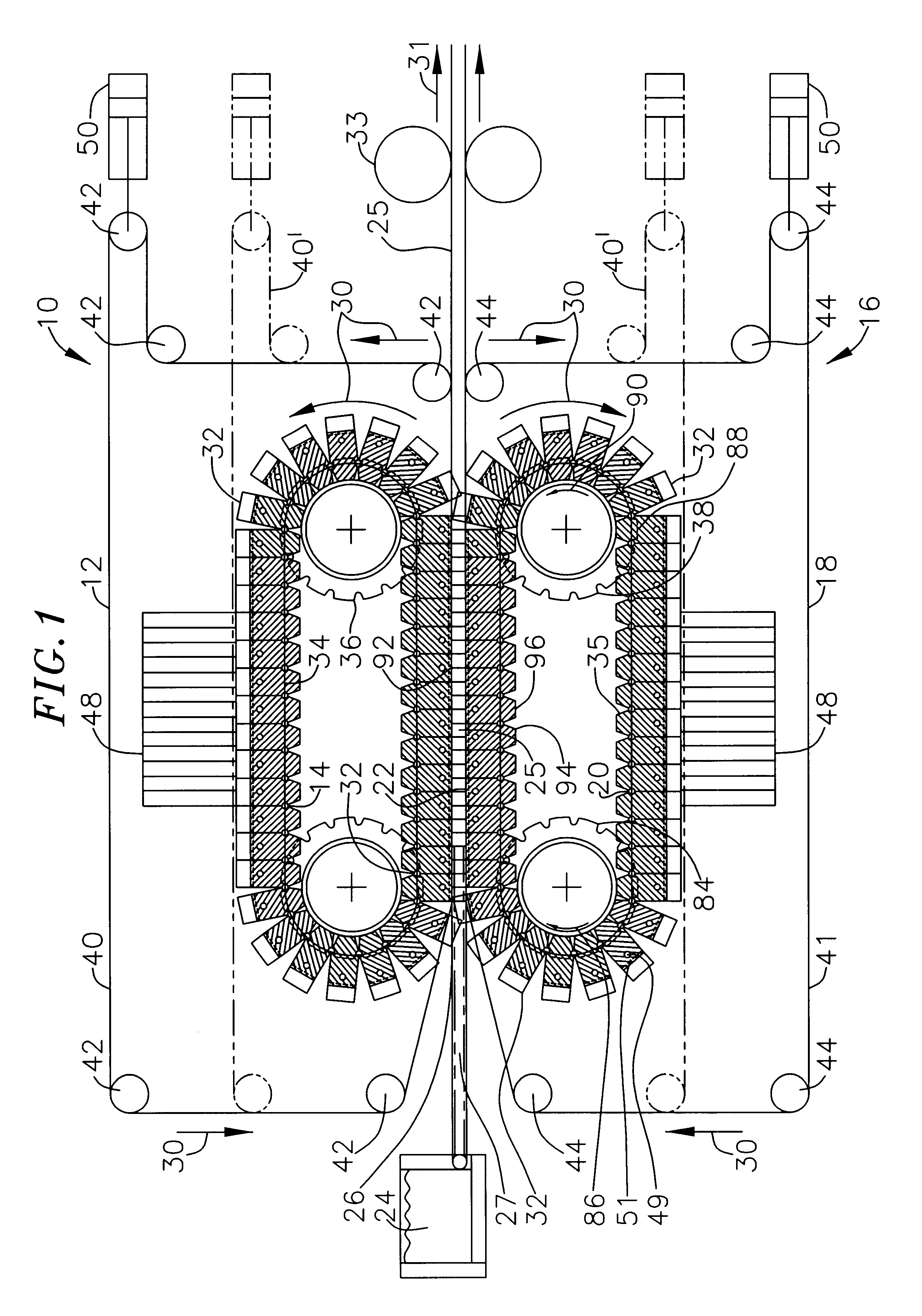
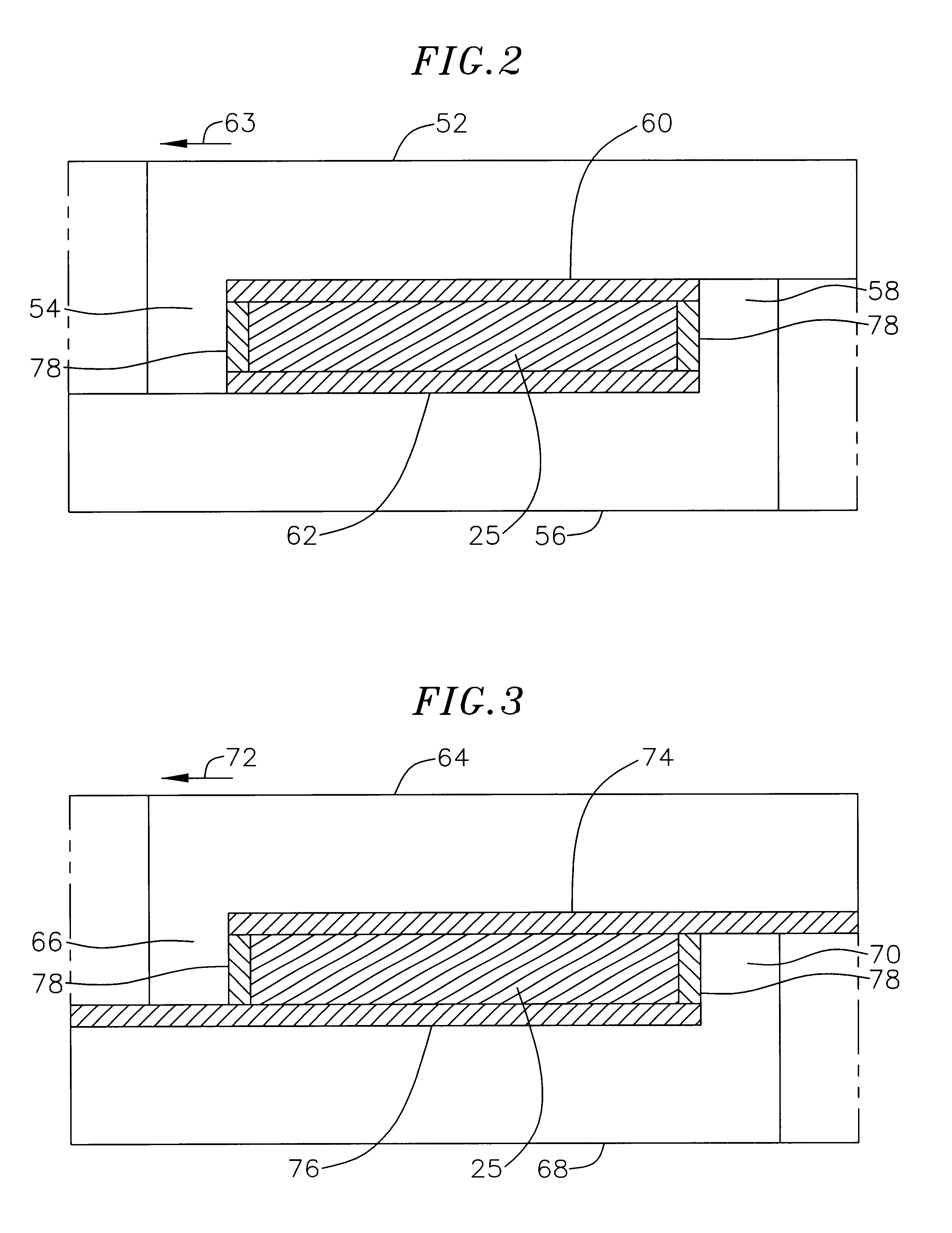
There is, therefore, provided in the practice of this invention a novel continuous caster comprising a headbox and a mold channel defined between two endless chain assemblies. The headbox is positioned at an opening of the mold channel, and molten metal is fed through the headbox to the mold channel. Each chain of the two endless chain assemblies has a protrusion at an opposite side of the chains defining a width and depth of the mold channel. At least one of the endless chain assemblies is movable relative to the other chain assembly, so that the width of the mold channel can be adjusted.
The invention is further directed to a novel continuous caster comprising first and second mold assemblies having first and second moving chains and belts moving in first and second closed chain and belt paths, respectively. The chain paths are internal relative to the belt paths and the corresponding belt and chain paths join over at least the part of their paths where the first and second paths pass in close proximity to define a mold channel. Because the belt operates externally from the chain, the smooth belt defines the surface of the mold channel and prevents finning. A headbox and tip are provided at the opening of the mold channel to supply molten metal to the mold channel.
Another novel method is provided according to the present invention for compensating for volumetric changes of a metal alloy to prevent undesirable deformation, abnormalities in the microstructure, and enhance cooling as the metal alloy shrinks from cooling during a continuous casting process on a chain caster having upper and lower mold assemblies defining a mold channel therebetween. The volumetric changes are compensated for by adjusting the depth of the mold channel throughout its length. This is accomplished by pressing a plurality of slidable upper and lower legs held in slots of the mold blocks against opposing mold blocks of the other assembly. The legs of the upper assembly are on opposite sides of the lower assembly. This is further accomplished by tilting one of the mold assemblies relative to the other to adjust the depth of the mold channel. Preferably, one of the mold assemblies is tilted relative to the other mold assembly to decrease the depth of the mold channel at the exit thereby compressing the resilient members near the exit of the chain caster.

Problems solved by technology

The cooling is, however, somewhat inefficient, and the thickness of the strip varies because of the lack of stiffness in the belt.
To prevent variations in the thickness and shape of the strip, the molten metal must be supplied to the mold at a low pressure which effects the casting process and causes surface and shape problems as well as deficiencies in the metal structure.
This process is, however, subject to other deficiencies.
The presence of fins on the molded strip interferes with the subsequent formation processes, such as rolling, to which the molded metal might be subjected.
To adjust the width of the strip, different widths of chains must be kept in stock or continuous, expensive, adjustable width side dams which are movable across the width of the blocks must be provided.
Because of the weight and bulk of the chain, the change is a difficult, time consuming, and extremely costly procedure.
It has also been difficult to obtain high accuracies of strip thickness / shape with the continuous casting machines.
The metal may even lose contact with the mold channel.
This slows cooling thus requiring a longer mold channel, and under some circumstances, this can lead to undesirable variations in thickness and other shape deformations.
More frequently, this has adverse effects on the microstructure of the cast product.

Method used


Image

  • Continuous chain caster and method
  • Continuous chain caster and method
  • Continuous chain caster and method

Examples


Embodiment Construction

The continuous caster shown in FIG. 1 comprises an upper mold assembly, generally designated 10, which includes an upper endless belt 12 and an upper endless chain 14 which travel in upper closed belt and chain paths at synchronized speeds. The endless belt is formed from a strip of metal that is cut to length and welded end to end. Thus, the mold assembly for the preferred embodiment can also be referred to as an endless belt and chain assembly. A lower mold assembly, generally designated 16, includes a lower endless belt 18 and a lower endless chain 20 traveling in lower closed belt and chain paths. The two mold assemblies meet and move generally parallel to each other in the casting region to form a rectangular mold channel 22 in between the mold assemblies, and a headbox 24 is positioned at an opening 26 of the feed end of the continuous caster. The belts extend across the entire width of the mold channel. The headbox continuously introduces molten metal to the mold channel thro...


PUM

PropertyMeasurementUnit
Poweraaaaaaaaaa
Poweraaaaaaaaaa
Lengthaaaaaaaaaa

Abstract

A continuous chain caster has upper and lower mold assemblies comprising endless belts and chains traveling at synchronized speeds. The mold assemblies meet to form a mold channel which is filled with molten metal from a headbox and feed tip. As the molten metal passes through the mold channel, the metal solidifies into the shape of the mold channel. Each belt is positioned outside the corresponding chain so that the smooth surface of the belt defines the surface of the mold channel thereby preventing the formation of fins between mold blocks which make up the chain, protecting the chain blocks, and neutralizing deformations in the chain blocks. The upper and lower blocks of the chains have protrusions at opposite ends which engage the opposing blocks to form the sides of the mold channel. By sliding the chains relative to each other, the width of the mold channel is adjustable. Further, the gauge of the mold channel is adjustable over the length of the channel by tilting one mold assembly relative to the other, so that the gauge at one end of the caster is greater than at the other end of the caster. In this embodiment, the protrusions are replaced with retractable legs which are held against the opposing block with a resilient member. The legs move in and out of slots in the blocks as the gauge of the channel mold is decreased and increased respectively.

Description

BACKGROUND OF THE INVENTIONThis invention relates to continuous casting apparatuses and methods.Continuous casting of metals and metal alloys of various kinds, both ferrous and nonferrous, has been undertaken for many years. The majority of the prior art discloses machines in which casting is performed by discharging molten metal between a pair of rollers which are continually cooled. It is possible to cast vertically downward, downward at an angle, or horizontally.Continuous casting of metals is undertaken by two common methods that are similar in some respects. Briefly, continuous casting is performed by means of endless members e.g. mold blocks mounted on or forming continuous chains, or endless belts with moving side dams disposed between the belts. The endless members which are typically disposed horizontally or slanted at a small angle from the horizontal serve as the mold for the cast metal, e.g., billet, slab, sheet, plate, or strip. The endless members, moving in non-circul...

Claims


Application Information

Patent Timeline
IPC IPC(8): B22D11/06
CPCB22D11/0608
Inventor BRAUN, CURTROMANOWSKI, CHRISTOPHER A.SPEED, BOBBY BRUCEPOST, PIETER F.
Owner HUNTER DOUGLAS IND BV
Learn More