
Multiple effect pyrotechnic shell

a pyrotechnic shell and multi-effect technology, applied in the field of pyrotechnic devices, can solve the problems of tertiary and higher-level breaks that cannot be controlled, break shells that fail to include features which permit tertiary and higher-level breaks, and the limitations of combining more than one effect or breaking into a single artillery shell, etc., to achieve the effect of inhibiting the occurrence of ground explosions

Inactive Publication Date: 2004-09-21
JAKES FIREWORKS
View PDF23 Cites 9 Cited by
  • Summary
  • Abstract
  • Description
  • Claims
  • Application Information

AI Technical Summary

Benefits of technology

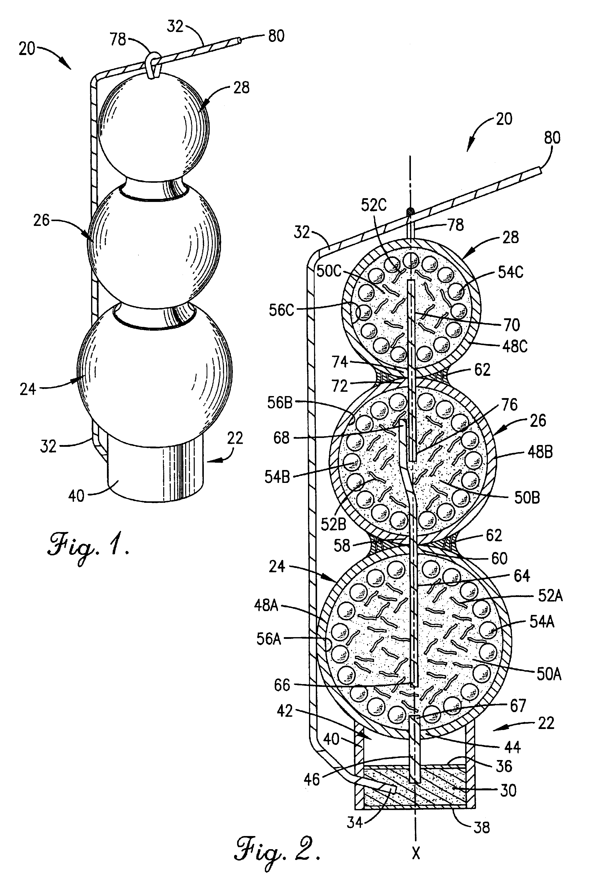
In a preferred embodiment, the secondary break weight is less than the primary break weight, and the tertiary break weight is less than the secondary break weight. Preferably, the center of gravity of the shell is spaced from and located below a vertical midpoint of the shell. The preferred embodiment also includes two internal timing fuses. A primary timing fuse extends from the primary break to the secondary break, and a secondary timing fuse extends from the secondary break to the tertiary break. The two timing fuses are preferably spaced apart within the secondary break. The shell also includes a lift chamber containing a lift charge. The lift chamber is attached to the bottom of the primary break to further inhibit tumbling.
In an alternate embodiment, the shell includes at least one break, and fuse fragments are distributed within the hull of the break. The fuse fragments act as filler and add an additional effect. Preferably, the fuse fragments are substantially evenly distributed within the hull, and secondary and tertiary breaks are also provided having fuse fragments within their respective hulls.
Accordingly, it is an object of the present invention to provide an improved multiple effect pyrotechnic shell which inhibits the occurrence of ground explosions.

Problems solved by technology

However, the industry has encountered limitations in combining more than one effect or break into a single artillery shell.
However, the two break shell fails to include features which control the direction which the secondary breaks are projected by the primary breaks.
Further, the two break shell fails to include features which would permit tertiary and higher level breaks.

Method used


Image

  • Multiple effect pyrotechnic shell
  • Multiple effect pyrotechnic shell

Examples


Embodiment Construction

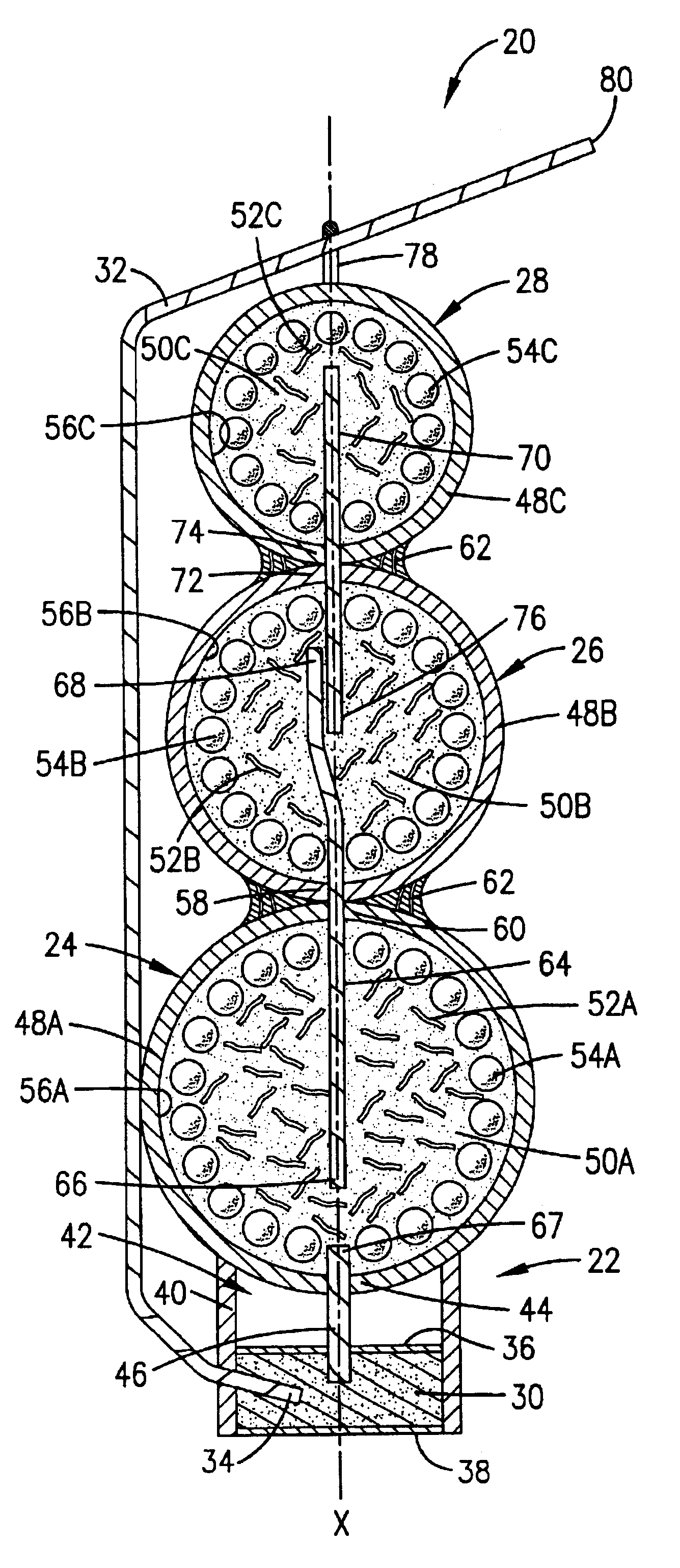
Referring to the drawings in greater detail, FIGS. 1 and 2 show a multiple effect pyrotechnic shell 20 constructed in accordance with a preferred embodiment of the present invention. The shell 20 broadly includes a lift chamber 22, primary break 24, secondary break 26, and tertiary break 28. The lift chamber 22 and breaks 24-28 are weighted to inhibit tumbling, thereby reducing the occurrences of ground explosions while providing the capability to display at least three effects.

The lift chamber 22 contains a lift charge 30 sized to project the shell to a sufficiently high altitude for explosion of the breaks 24-28. An elongated and external safety fuse 32 has a terminal end 34 embedded in the lift charge 30. The lift charge 30 and terminal end 34 of the external fuse 32 are held between upper and lower closures 36, 38 and an outer cylindrical wall 40 which attaches to the primary break 24. An open area 42 is preferably left between the upper closure 36 and the bottom 44 of the prima...


PUM


Abstract

A multiple effect pyrotechnic shell (20), having a lift chamber (22), primary break (24), secondary break (26), and a tertiary break (28) has a desired weight distribution to inhibit tumbling. The secondary break weight is less than the primary break weight, and the tertiary break weight is less than both the primary and secondary break weights. Thus, the center of gravity of the shell (20) is positioned below a midpoint of the shell height. A first timing fuse (46) extends from a lift charge (30) into a primary break charge (50A) of the primary break (24), and a primary internal timing fuse (64) extends from the primary break (24) to the secondary break (26). Further, a secondary internal timing fuse (70) extends from the secondary break (26) to the tertiary break (28). Fuse fragments (52) are preferably disbursed within the break hulls (48) to provide filler and add an additional effect to each break (24-28).

Description

FIELD OF THE INVENTIONThis invention relates to pyrotechnic devices and, more particularly, to class C fireworks in the form of artillery shells having multiple breaks.BACKGROUND OF THE INVENTIONThe pyrotechnic industry is continuously developing new pyrotechnic effects for class C fireworks. Class C fireworks are those intended for use by ordinary consumers. These efforts have resulted in artillery shell type fireworks with many colors and dispersal patterns. However, the industry has encountered limitations in combining more than one effect or break into a single artillery shell. For example, class C fireworks are restricted to a total of 40 grams of break charge, and the secondary breaks of the shell should not be projected by explosion of the primary breaks so that the secondary breaks explode on or near the ground. One multiple effect shell includes two breaks of equal size. However, the two break shell fails to include features which control the direction which the secondary b...

Claims


Application Information

Patent Timeline
IPC IPC(8): F42B4/06F42B4/00
CPCF42B4/06
Inventor WU, FRANCISMARIETTA, MICHAEL
Owner JAKES FIREWORKS
Learn More