Stationary exercise apparatus having a preferred foot platform path

a technology of stationary exercise and platform path, which is applied in the direction of sport apparatus, gymnastic exercise, cycle, etc., can solve the problems of difficult to ascend and descend the movement of the knees and ankles, the knees are difficult to lift or exaggerate the vertical movement of the lower legs, and the knees are difficult to exercise the upper body muscle group. , to achieve the effect of promoting exercise of the upper body muscle group

Inactive Publication Date: 2005-09-27
NAUTILUS INC
View PDF37 Cites 50 Cited by
  • Summary
  • Abstract
  • Description
  • Claims
  • Application Information

AI Technical Summary

Benefits of technology

[0012]In another alternate embodiment of the present invention, each linkage assembly may comprise two pairs of parallel links. The first pair of parallel links act in a similar fashion to the first link of the preferred embodiment while the second set of parallel links act in a similar fashion to the second link in the preferred embodiment. However, since two parallelograms are established through the use of parallel links connected by a pivot plate between the two pairs of links, the foot platform remains parallel with a reference plane, such as the floor, while moving through a predetermined substantially elliptical path. In addition, one link of the second pair of links of each linkage assembly may be longer and used as an arm member to promote exercise of the upper body muscle group at the same time.

Problems solved by technology

However, it can over prolonged use overstress the knees.
First, they require excessive lifting of the knees or an exaggerated vertical movement of the lower legs.
Alternatively, the devices which do tend to promote a more natural movement of the knees and ankles are difficult to ascend and descend because of the configuration of the devices.
Additionally, while certain prior art devices have attempted to imitate a more natural movement of the knees or ankles, they have failed to provide an accurate simulation.

Method used


Image

  • Stationary exercise apparatus having a preferred foot platform path
  • Stationary exercise apparatus having a preferred foot platform path
  • Stationary exercise apparatus having a preferred foot platform path

Examples


Embodiment Construction

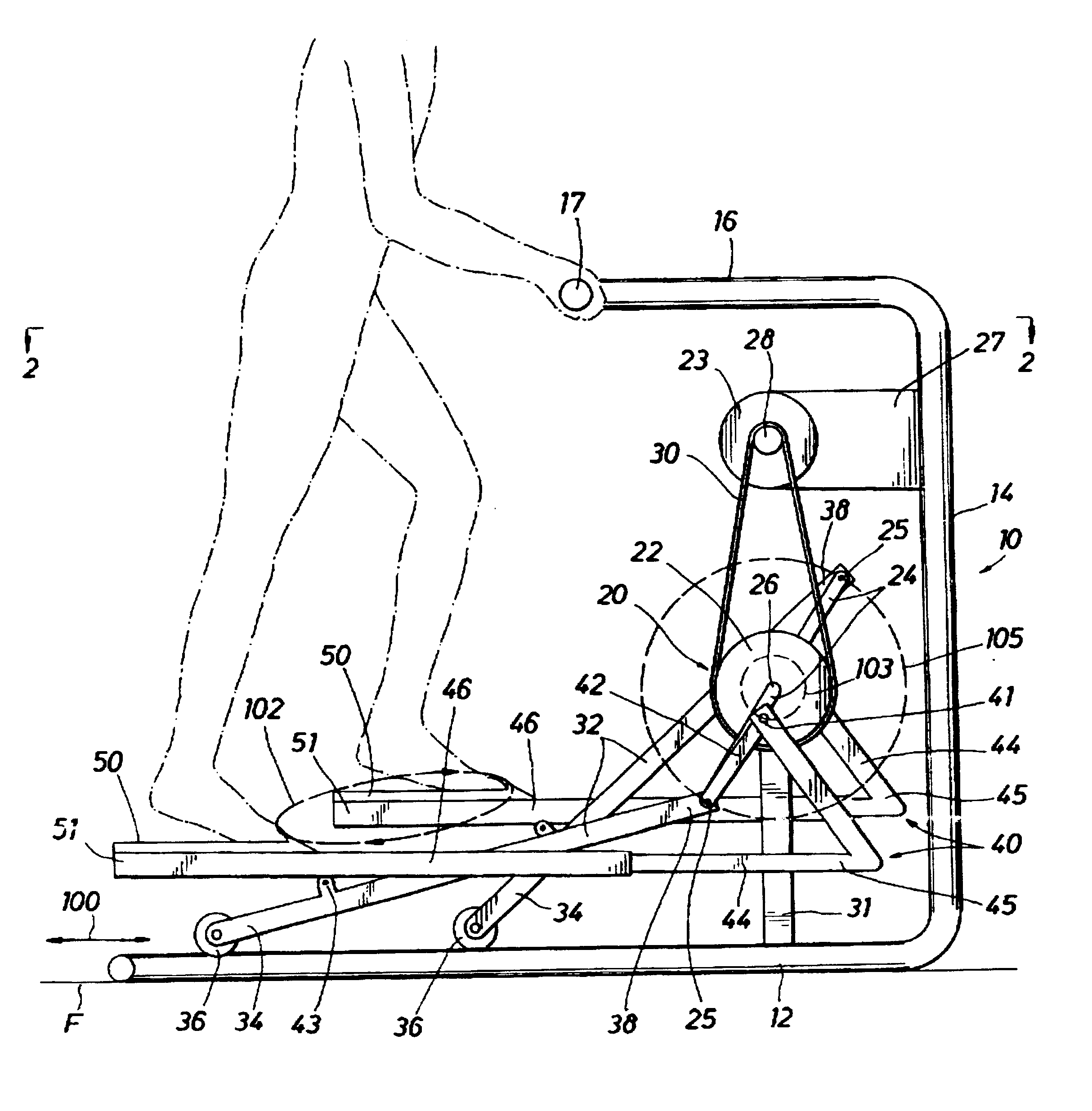
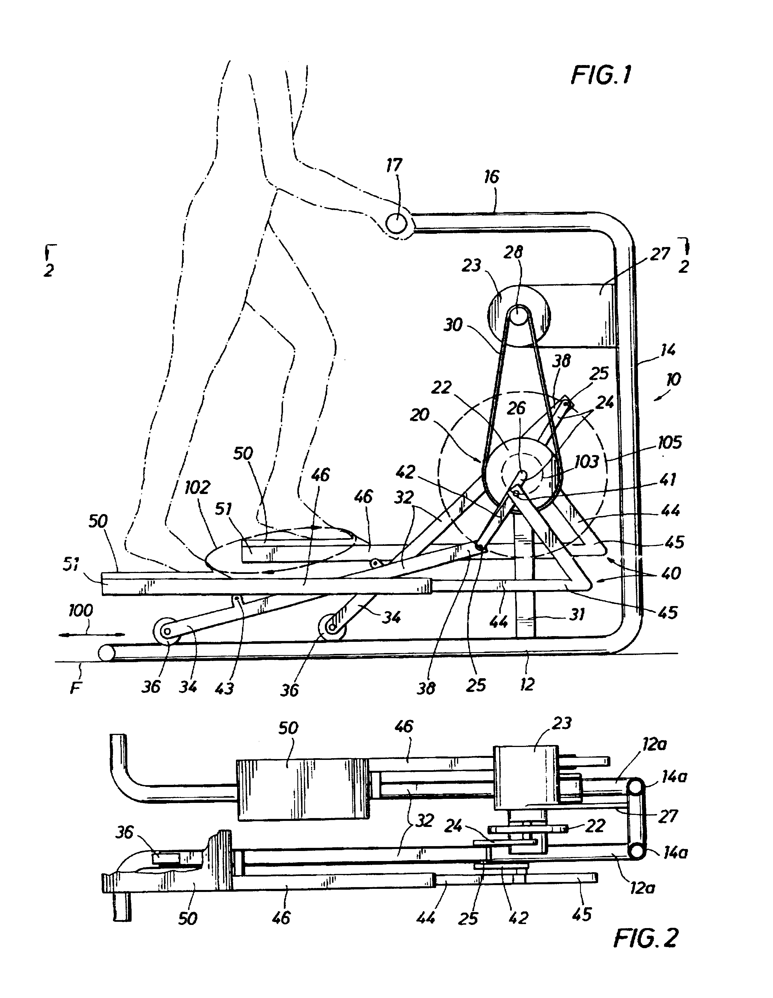
[0022]Referring to FIGS. 1 and 2, a frame 10 is shown comprising a base portion 12, a mid portion 14, and a top portion 16. Referring briefly to FIG. 2, the frame 10 comprises two bottom portions 12a and 12b, two mid portions 14a and 14b, and two top portions (not shown). In essence, the frame is comprised of two separate bents “a” and “b”. Obviously, variations can be made to frame 10 as disclosed without departing from the spirit of the invention.

[0023]A coupling system 20 is fixed relative to the frame and comprises a pulley 22, crank members 24, resistant brake 23, sheave 28 and belt 30. A plurality of operative members are coupled with the coupling system 20 to control the elliptical path of movement of the foot platforms 50. The plurality of operative members include a pair of reciprocating members 32 and a pair of primary links 44. Two reciprocating members 32 are positioned in the lower proximity of frame 10. Each reciprocating member 32 has one end 34 which is adapted to mo...


PUM


Abstract

A stationary exercising apparatus which promotes cardiovascular exercise yet minimizes impact on critical joints through the generation of a predetermined elliptical path movement while maintaining foot platforms substantially parallel with the floor. A base structure supports a pair of reciprocating members which are displaced in a horizontal direction parallel with the floor at one end yet reciprocate in circular motion at the other end through a coupling system attached to the frame. A linkage assembly is included which operates in conjunction with the reciprocation of one end of the reciprocating members to maintain the foot platforms substantially parallel with a reference plane while revolving the foot platforms in a substantially elliptical path. The apparatus may include additional linkage to facilitate a corresponding upper body exercise involving movement of the arms along a predetermined arc.

Description

RELATED APPLICATION[0001]This application is a continuation of application Ser. No. 08 / 497,612 filed Jun. 30, 1995 now U.S. Pat. No. 5,593,372 for Stationary Exercise apparatus Having A Preferred Foot Platform Path, which was a continuation-in-part of U.S. application Ser. No. 08 / 377,846 filed Jan. 25, 1995 now U.S. Pat. No. 5,573,480 entitled Stationary Exercise Apparatus.BACKGROUND OF THE INVENTION[0002]1. Field of the Invention[0003]The present invention relates to an improved stationary exercising apparatus. More particular, the invention relates to an improved exercising apparatus which enables the user to move his feet in an elliptical path while foot platforms remain substantially parallel with a reference plane.[0004]2. Description of the Prior Art[0005]Stair climbing is a popular form of exercise for the cardiovascular system. However, it can over prolonged use overstress the knees. Walking is also a popular form of exercise but it does not load the cardiovascular system to...

Claims


Application Information

Patent Timeline
Patent Type & Authority Patents(United States)
IPC IPC(8): A63B22/00A63B22/04A63B69/16A63B23/035A63B23/04B62K3/00B62M1/12B62M1/24
CPCA63B22/001A63B22/0664A63B2022/0676B62M1/12B62M1/26
Inventor RODGERS, JR., ROBERT E.
Owner NAUTILUS INC
Why Eureka
Try Eureka