Method and apparatus for alerting an operator of a motor vehicle to an incoming radar signal
a technology for detecting radar signals and operators, applied in the field of police radar detectors, can solve problems such as annoying false alarms of motor vehicle operators, false alarms generated by conventional radar detectors, and source of annoying false alarms
- Summary
- Abstract
- Description
- Claims
- Application Information
AI Technical Summary
Benefits of technology
Problems solved by technology
Method used
Image
Examples
first embodiment
3.1 Description of a First Embodiment
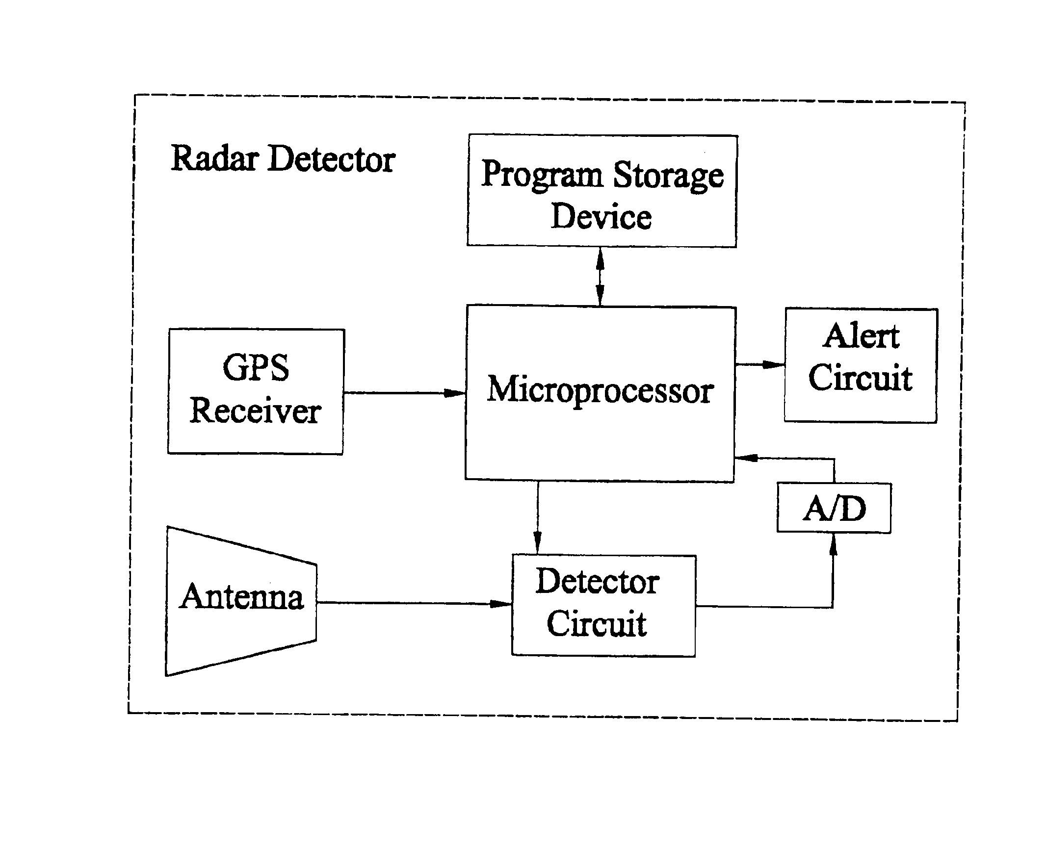
[0013]One embodiment of the novel radar detector is shown in FIG. 1. The radar detector includes an antenna that is coupled to a detector circuit. The detector circuit, which may be controlled by the microprocessor of FIG. 1, collects the signals from the antenna, detects the incoming signals, and distinguishes valid radar signals from electrical noise. The detector circuit may be any appropriate radar detector circuit capable of generating an output signal which indicates the strength, the presence, and / or the frequency of incoming radar signals. While the detector circuit may operate autonomously, operation and control of the detector circuit may be performed by the microprocessor. For example, the microprocessor may control the detector as is known in the art so that radar signals in the different frequency bands allocated to police radar signals are detected. Such detector circuits can take a wide variety of forms and can include amplifiers, ...
second embodiment
3.2 Description of a Second Embodiment
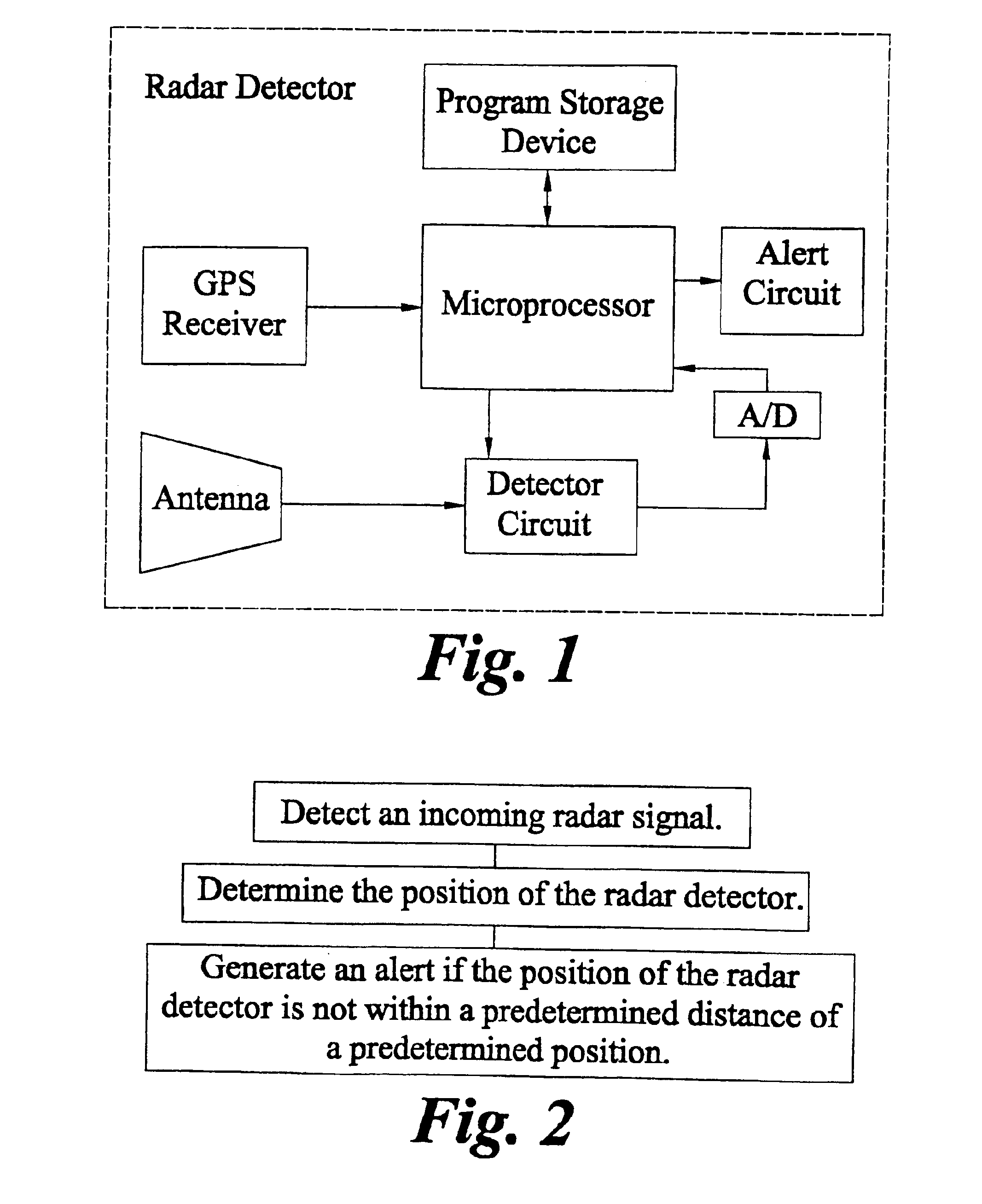
[0020]One method of operating the radar detector of FIG. 1 is shown in FIG. 2. In this embodiment, the radar detector first detects an incoming radar signal. Next, the position of the radar detector is determined. Then, an alert is generated if the position of the radar detector is not within a predetermined distance of a predetermined position.
[0021]By utilizing the above method, many false alarms may be eliminated. For example, if the position of a microwave automatic door opener is programmed into the radar detector and the radar detector detects an incoming signal when the radar detector's position is near the automatic door opener, then it is likely that the source of the incoming radar signal is the automatic door opener and not a police radar. Thus, using the method of FIG. 2, an alert would not be generated for the detector radar signal.
[0022]The programming of predetermined positions may be accomplished by depressing one or more buttons...
third embodiment
3.3 Description of a Third Embodiment
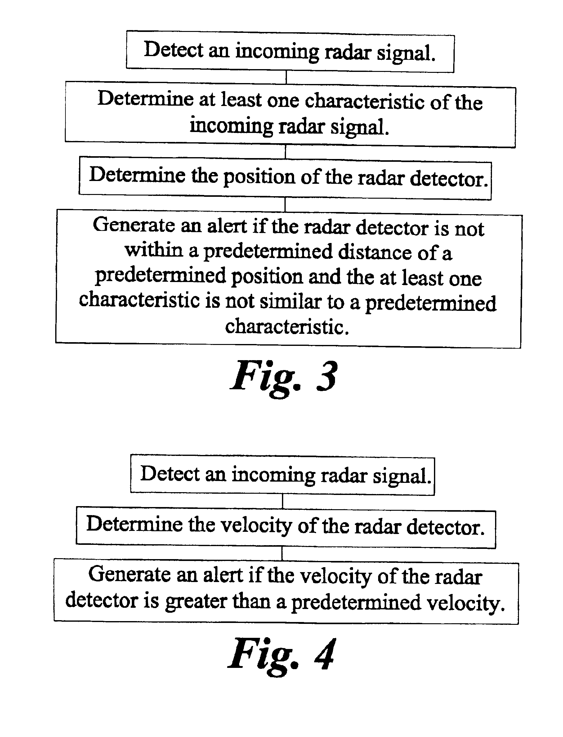
[0025]The simple method of operating a radar detector shown in FIG. 2 can be improved as shown in FIG. 3. In this embodiment, the after the radar detects an incoming radar signal it determines a characteristic of the radar signal. For example, the radar detector may determine the frequency and / or the signal strength of the incoming radar signal. Next, the position of the radar detector is determined. Then, an alert is generated if the radar detector is not within a predetermined distance of a predetermined position and the characteristic is not similar to a predetermined characteristic.
[0026]By utilizing this method, many false alarms may be eliminated. For example, the location of a microwave automatic door opener and the frequency of the radar signal transmitted by the door opener are first programmed into a radar detector. Assume that a police radar is being transmitted near the location of the microwave automatic door opener. Because the poli...
PUM
 Abstract
Description
Claims
Application Information
 - R&D
- Intellectual Property
- Life Sciences
- Materials
- Tech Scout
- Unparalleled Data Quality
- Higher Quality Content
- 60% Fewer Hallucinations
Browse by: Latest US Patents, China's latest patents, Technical Efficacy Thesaurus, Application Domain, Technology Topic, Popular Technical Reports.
© 2025 PatSnap. All rights reserved.Legal|Privacy policy|Modern Slavery Act Transparency Statement|Sitemap|About US| Contact US: help@patsnap.com


