Low profile inductive component

a technology of inductive components and low profile, which is applied in the field of low profile surface mountable inductive components, can solve the problems of low profile components, limited technology, and more powerful effects

Inactive Publication Date: 2007-01-02
COILCRAFT
View PDF49 Cites 13 Cited by
  • Summary
  • Abstract
  • Description
  • Claims
  • Application Information

AI Technical Summary

Benefits of technology

[0009]A low profile inductive component in accordance with the invention comprises a low profile body having spread apart soldering pads for electrically and mechanically attaching the body to a printed circuit board. The body defines an aperture between the pads. A core is disposed in the aperture. A wire is wound around the core and has first and second ends connected to the soldering pads. The core has integral flan

Problems solved by technology

Often times, applications specifically require “low profile” components due to constraints in height and width.
Unfortunately, the technology is often limited due to the inability to make certain components smaller, faster, or more powerful.
This technique left half of the PCB unpopulated because one side had to be reserved for solder pads and solder.
As a result of this advancement in technology, the current electronic circuits are mainly limited by the size of components used on the PCB.
Unfortunately, there are some electronic components that can simply not be produced any smaller than they currently a

Method used


Image

  • Low profile inductive component
  • Low profile inductive component
  • Low profile inductive component

Examples


Embodiment Construction

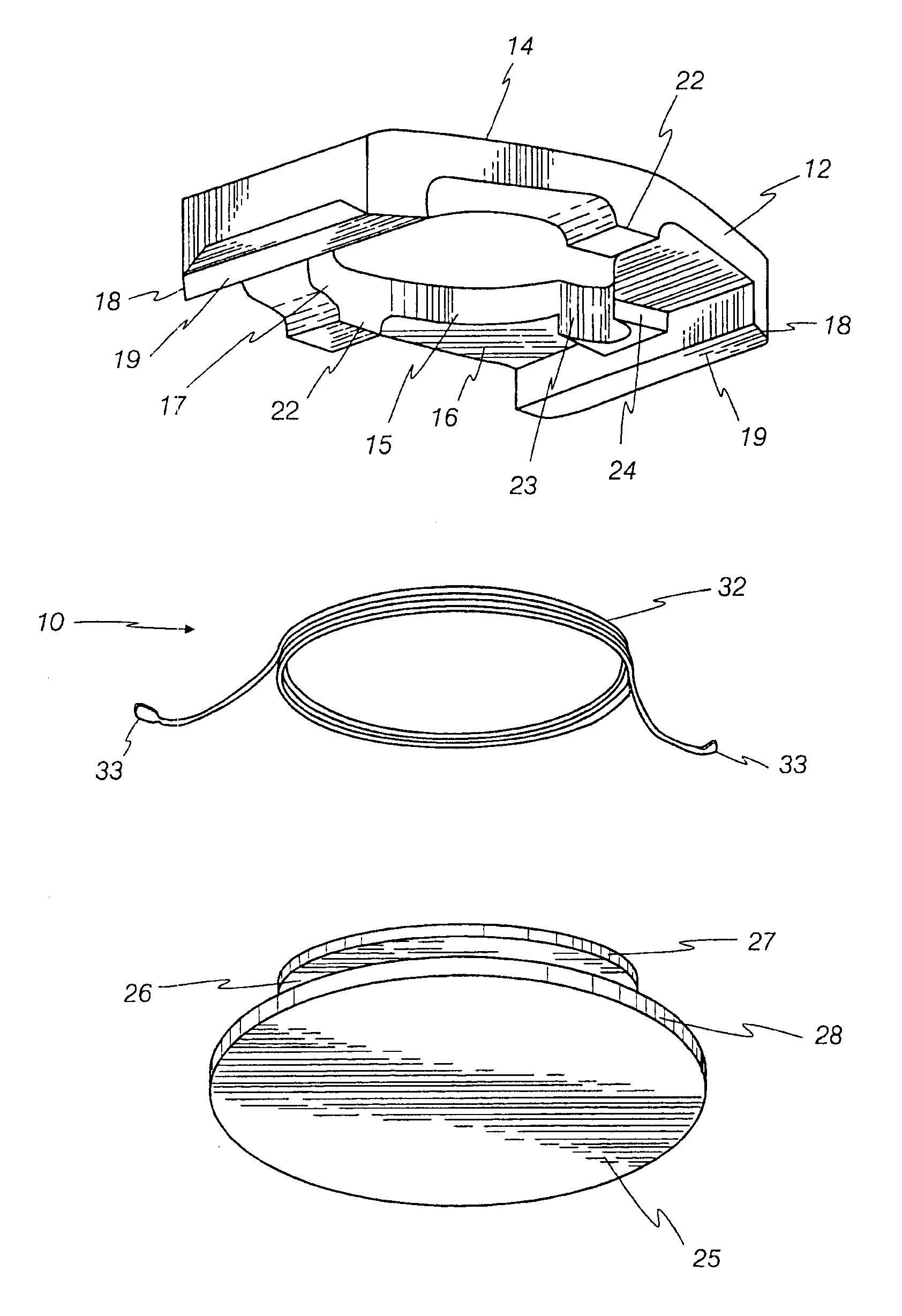
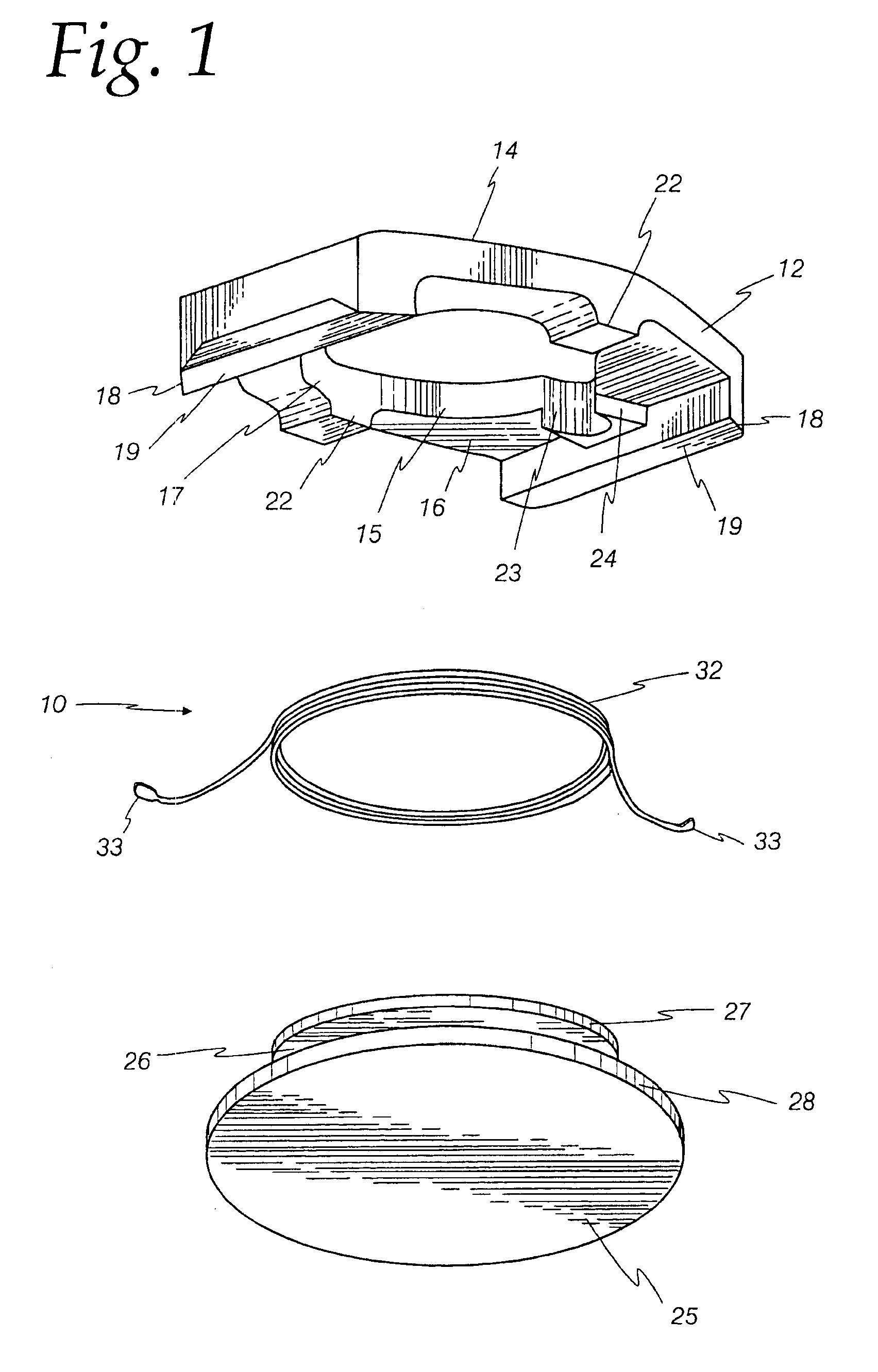
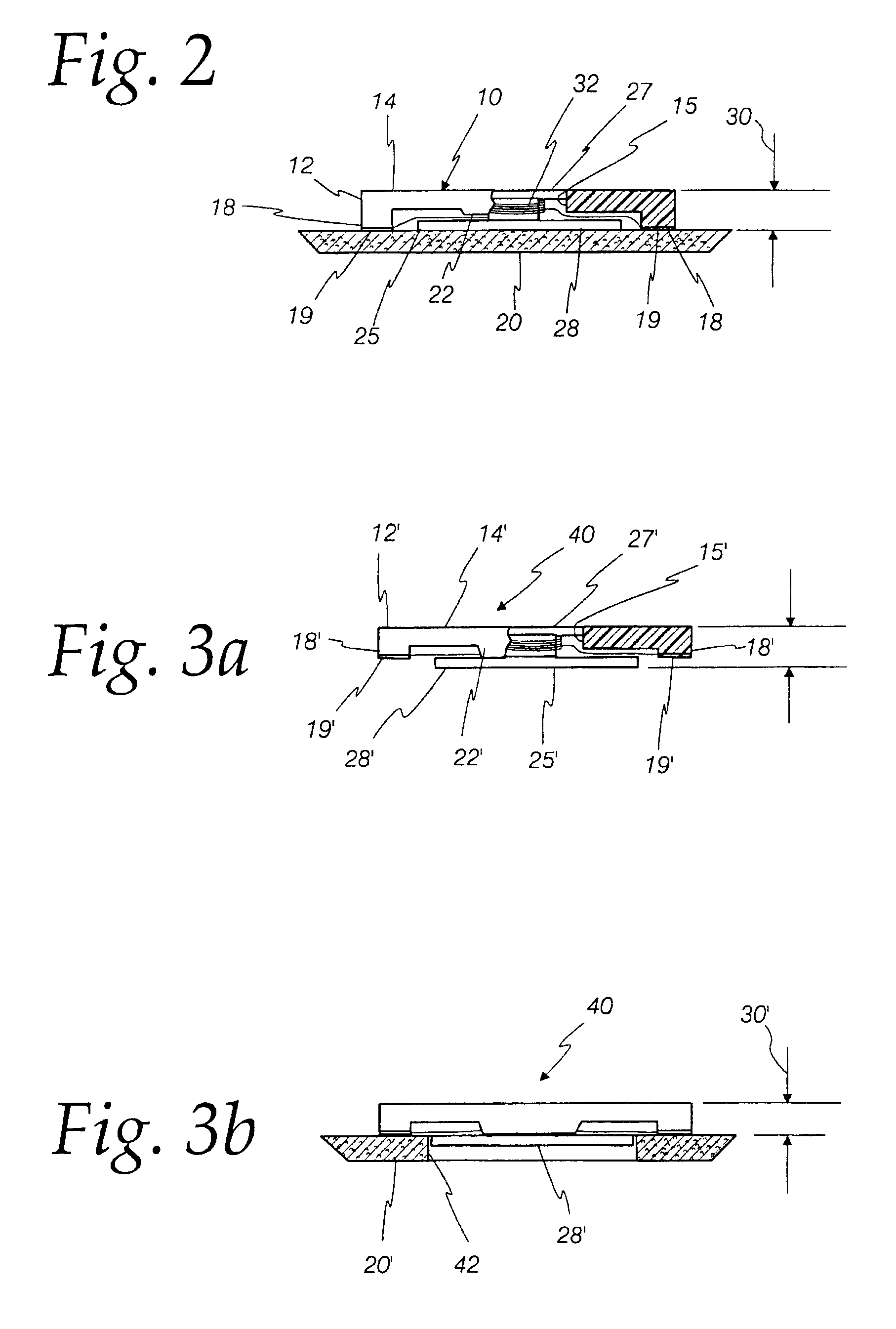
[0017]Turning first to FIGS. 1 and 2, a low profile inductive component in accordance with the invention for mounting above the printed circuit board (PCB) is shown generally at reference numeral 10. For convenience, the inductive component is described as it would be positioned on the upper surface of a PCB.

[0018]In FIGS. 1 and 2, the low profile inductive component 10 includes a low profile body 12 made of an insulating material, such as a non-conductive plastic or ceramic. The body 12 has a polygonal shape, such as a hexagon, and is defined by a smooth planer top 14 and a bottom 16. The body 12 defines an aperture 15 passing directly through the center of the top 14 and the bottom 16, and having an inner wall 17.

[0019]A pair of legs 18 extend downward from opposite ends of the body 12. Soldering pads 19 are located at the bottom of the legs 18, which are made of a conductive material, such as metal, for electrically and mechanically attaching the low profile inductive component 1...


PUM

PropertyMeasurementUnit
Lengthaaaaaaaaaa
Heightaaaaaaaaaa
Heightaaaaaaaaaa

Abstract

A low profile inductive component in accordance with the disclosure set forth here comprises a low profile body having spread apart soldering pads for electrically and mechanically attaching the structure to a printed circuit board and defining an aperture between the pads. A magnetic core is disposed in the aperture. A wire is wound around the core having a first and second end connected to the pads. One end of the core is disposed in the aperture of the low profile body and its other end, which is larger than the aperture, is spaced from the body by spacers extending from the body.

Description

FIELD OF THE INVENTION[0001]This invention relates generally to electronic components, and more particularly concerns low profile surface mountable inductive components.BACKGROUND[0002]The electronics industry is continually called upon to make products smaller and more powerful. Applications such as mobile phones, portable computers, computer accessories, hand-held electronics, etc., create a large demand for smaller electrical components. These applications further drive technology to research new areas and ideas with respect to miniaturizing electronics. Often times, applications specifically require “low profile” components due to constraints in height and width. Unfortunately, the technology is often limited due to the inability to make certain components smaller, faster, or more powerful. Nowhere can this be seen more than in the struggle to manufacture smaller electrical circuits.[0003]Originally, components were mounted on a printed circuit board (PCB) by inserting the leads...

Claims


Application Information

Patent Timeline
IPC IPC(8): H01F27/02H01F27/30H01F17/04H01F27/29H05K1/18H05K3/34
CPCH01F27/292H01F27/027H01F17/045Y10T29/4902H05K1/18
Inventor BOYTOR, JAMES G.GIRBACI, CATALIN C.GOGNY, HELEN O.
Owner COILCRAFT
Why Eureka
Try Eureka