Fastener delivery tube

a technology of fastener and delivery tube, which is applied in the direction of conveyor parts, applications, transportation and packaging, etc., to achieve the effect of increasing the free space between the bells

Inactive Publication Date: 2008-06-24
EDWARDS CYRIL K
View PDF15 Cites 2 Cited by
  • Summary
  • Abstract
  • Description
  • Claims
  • Application Information

AI Technical Summary

Benefits of technology

[0030]The restraining force which the balls can apply to a fastener can be controlled, by ensuring that they are brought into contact with a friction pad, disposed so that all the balls in the loop have to pass by it in the course of a complete revolution or passage around a loop.
[0031]A fastener driving plu

Problems solved by technology

It has been found that, in circumstances where it is not possible to use a guidance tool, and where the fastener has an inadequate bearing surface on its major diameter, or where the length of the fastener is small relative to it

Method used


Image

  • Fastener delivery tube
  • Fastener delivery tube
  • Fastener delivery tube

Examples


Embodiment Construction

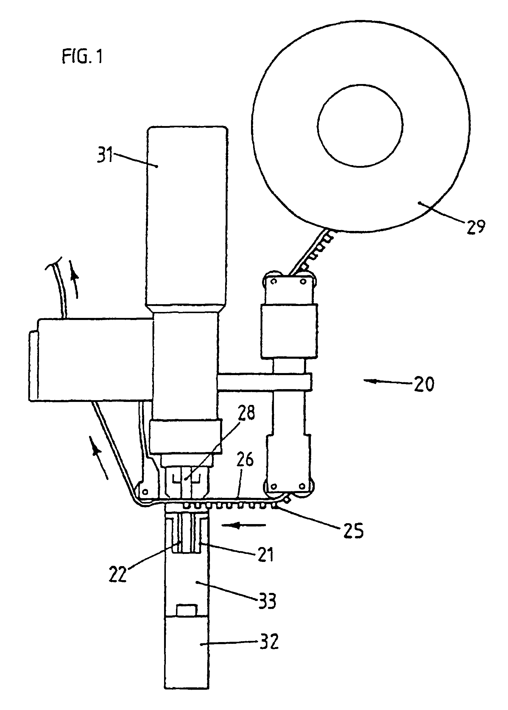
[0053]Referring to the drawings, and in particular FIG. 1, a fastener applicator 20 has a fluid-actuated ram 31, with a movable piston or plunger driving head 28 for contacting the head of an individual fastener 25 and driving the fastener 25 into a workpiece (not shown) mounted in the throat 33 of a C-frame 32.

[0054]For repetitive operation, fasteners 25 are transported to the driving plunger 28 as a linear succession in a carder tape 26, typically of flexible synthetic plastics, from a reservoir or supply spool or cartridge 29 to a position underneath the driving plunger 28.

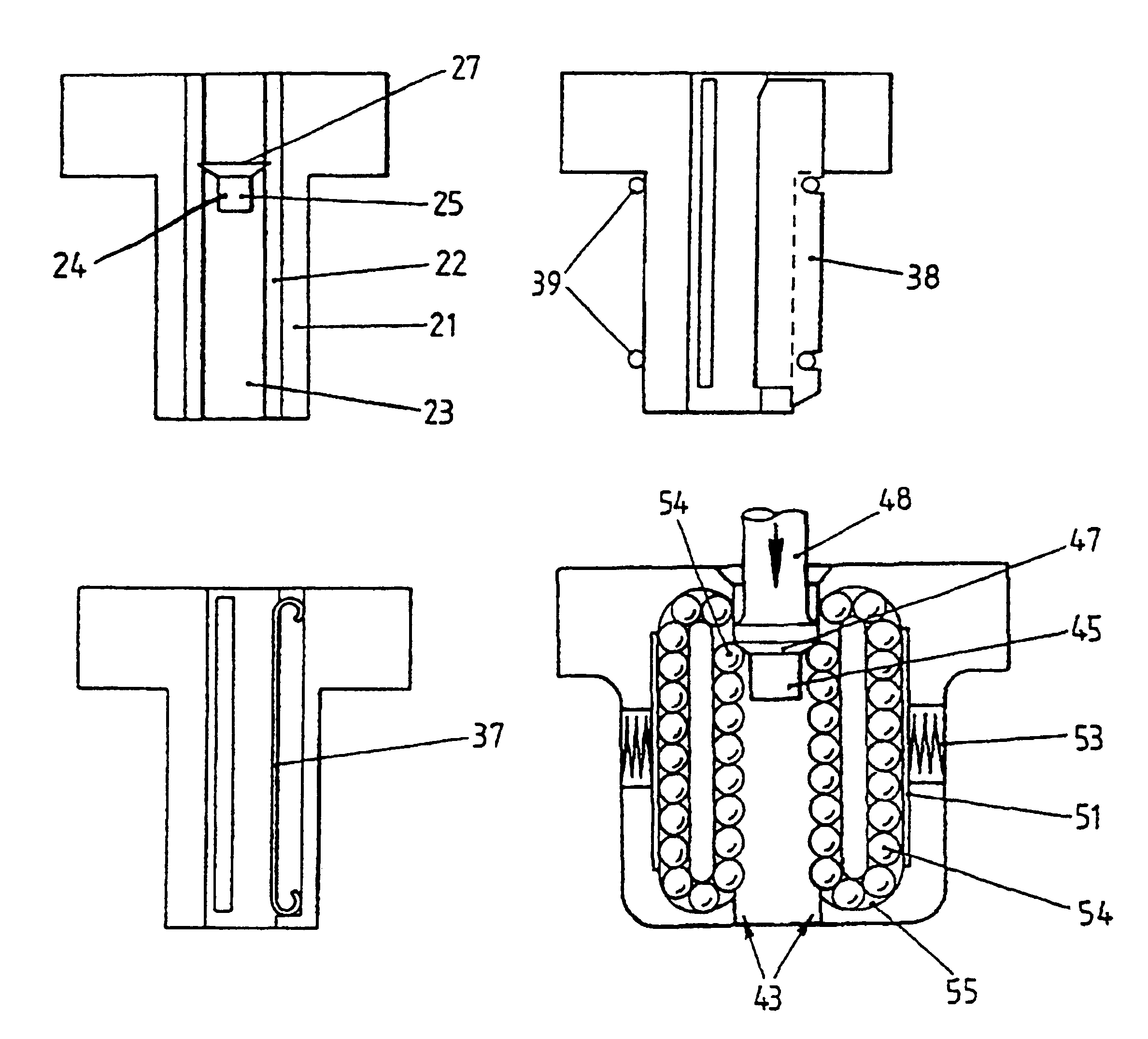
[0055]In order to gain access to a workpiece in positions where space is restricted, it is often necessary to release a fastener 25 from the carrier tape at a point remote from the workpiece and to use a delivery tube 21 to convey the fastener 25 to the point of application.

[0056]It is with such a delivery tube 21—and the interaction of its internal passage with the external profile of a fastener 25—that the pr...


PUM

PropertyMeasurementUnit
Forceaaaaaaaaaa
Diameteraaaaaaaaaa

Abstract

A fastener delivery tube (21) incorporates an internal guide (22)—such as a continuous sleeve lining, flexible, or resiliently deformable spring strips (34, 37, 38) or re-circulating balls (54)—forming a longitudinally movable constriction, inhibiting fastener free-fall through the tube and preserving fastener orientation, by maintaining fastener (25) contact with a driving plunger (28) in its passage there-through and upon exit there-from into contact with a workpiece.

Description

[0001]This application is a reissue of U.S. application Ser. No. 08 / 049,083, filed on Apr. 20, 1993, now U.S. Pat. No. 5,398,860.BACKGROUND OF THE INVENTION[0002]1. Field of the Invention[0003]This invention relates to the presentation of fasteners to workpieces. More specifically, it relates to fasteners which are to be machine applied and need to be fed, through a delivery tube, from a supply, such as a carrier tape, to a remote workpiece—often with restricted access.[0004]2. Description of the Prior Art[0005]It has been found desirable to provide such a delivery tube with the capability of exerting a controlled restraining force, sufficient to hold the fasteners in a desired orientation throughout their passage through the tube—but preferably without marking the fastener body.[0006]The term tube is used herein to embrace any configuration or disposition of chamber, enclosure or passageway.[0007]The term fastener is used herein to embrace a disparate variety of elements for joinin...

Claims


Application Information

Patent Timeline
IPC IPC(8): B21J15/32A44B19/42B21J15/00B21J15/36B23P19/00B25B23/10B65G47/24
CPCB21J15/32B21J15/323B25B23/10B65G47/24
Inventor EDWARDS, CYRIL K.
Owner EDWARDS CYRIL K
Why Eureka
Try Eureka