Capacity modulated scroll machine having one or more pin members movably disposed for restricting the radius of the orbiting scroll member

a scroll machine and capacity modulation technology, which is applied in the direction of positive displacement liquid engines, instruments, lighting and heating apparatus, etc., can solve the problems of increasing the cost of approach, reducing the compression ratio of compressors, and requiring additional space, so as to maximize the efficiency of compressors and/or refrigeration systems, maximize overall system efficiency, and increase efficiency

Inactive Publication Date: 2008-10-28
EMERSON CLIMATE TECH INC
View PDF50 Cites 39 Cited by
  • Summary
  • Abstract
  • Description
  • Claims
  • Application Information

AI Technical Summary

Benefits of technology

[0004]The present invention, however, overcomes these deficiencies in that it enables virtually a continuous range of unloading from 100 percent or full capacity down to virtually zero capacity utilizing only a single set of controls. Further, the system of the present invention enables the operating efficiency of the compressor and / or refrigeration system to be maximized for any degree of compressor unloading desired.
[0005]In the present invention, compressor unloading is accomplished by cyclically effecting axial or radial separation of the two scroll members for predetermined periods of time during the operating cycle of the compressor. More specifically, the present invention provides an arrangement wherein one scroll member is moved axially or radially toward and away from the other scroll member in a pulsed fashion to cyclically provide a leakage path across the tips or flanks of the wraps from higher pressure compression pockets defined by the intermeshing scroll wraps to lower pressure pockets and ultimately back to suction. By controlling the relative time between sealing and unsealing of the scroll wrap tips or flanks, virtually any degree of compressor unloading can be achieved with a single control system. Further, by sensing various conditions within the refrigeration system, the duration of compressor loading and unloading for each cycle can be selected for a given capacity such that overall system efficiency is maximized. For example, if it is desired to operate the compressor at 50 percent capacity, this can be accomplished by operating the compressor alternately in a loaded condition for five seconds and unloaded for five seconds or loaded for seven seconds and unloaded for seven seconds, one or the other of which may provide greater efficiency for the specific operating conditions being encountered.
[0006]The various embodiments of the present invention described below provide a wide variety of arrangements by which one scroll member may be axially or radially reciprocated with respect to the other to accommodate a full range of compressor unloading. The ability to provide a full range of capacity modulation with a single control system as well as the ability to select the duration of loaded and unloaded operation cooperate to provide an extremely efficient system at a relatively low cost.
[0007]Additionally, in order to even further improve system efficiency in some applications, it may be desirable to combine a delayed suction type of capacity modulation with the pulsed unloading approach mentioned above. For example, when operating conditions are such that system pressures just downstream of the discharge valve are at a level below the full load design level, the compression ratio of the compressor will result in pressure of the compressed fluid as it is discharged from the compression chamber being too high, a condition known as over-compression. The most efficient way to reduce capacity under these conditions is to reduce the compression ratio of the compressor and hence the pressure of the compressed fluid exiting the compression chamber such that it is equal to or only slightly above the system pressure just downstream of the discharge valve thus eliminating the lost work due to over-compression. However, if a further reduction in capacity is indicated by system condition once the over-compression condition has been eliminated, the use of a pulsed type of capacity modulation will be more efficient as it will avoid creation of a condition known as under-compression, that being a situation where the pressure of the compressed fluid as it leaves the compression chamber being below that of the system just downstream of the discharge valve. Thus, the present invention also includes a system in which both pulsed and delayed suction capacity modulation approaches are combined which result in even greater efficiencies for systems likely to encounter such operating conditions than could be achieved by either of the two capacity modulation approaches alone.
[0008]Additionally, the present invention may also incorporate a motor control module which will operate to control various operating parameters thereof to enhance its operating efficiency during periods when the motor load is reduced due to unloading of the compressor.
[0033]FIG. 45 is a schematic showing a means for reducing motor power consumption during periods when the compressor is operating in an unloaded condition in accordance with the present invention; and

Problems solved by technology

This method of capacity modulation actually reduces the compression ratio of the compressor.
While such systems are effective at reducing the capacity of the compressor, they are only able to provide a predetermined amount of compressor unloading, the amount of unloading being dependent upon the positioning of the unloading ports along the wraps.
While it is possible to provide multiple step unloading by incorporating a plurality of such ports at different locations, this approach becomes costly and requires additional space to accommodate the separate controls for opening and closing each set of ports.
For example, when operating conditions are such that system pressures just downstream of the discharge valve are at a level below the full load design level, the compression ratio of the compressor will result in pressure of the compressed fluid as it is discharged from the compression chamber being too high, a condition known as over-compression.

Method used


Image

  • Capacity modulated scroll machine having one or more pin members movably disposed for restricting the radius of the orbiting scroll member
  • Capacity modulated scroll machine having one or more pin members movably disposed for restricting the radius of the orbiting scroll member
  • Capacity modulated scroll machine having one or more pin members movably disposed for restricting the radius of the orbiting scroll member

Examples


embodiment 94

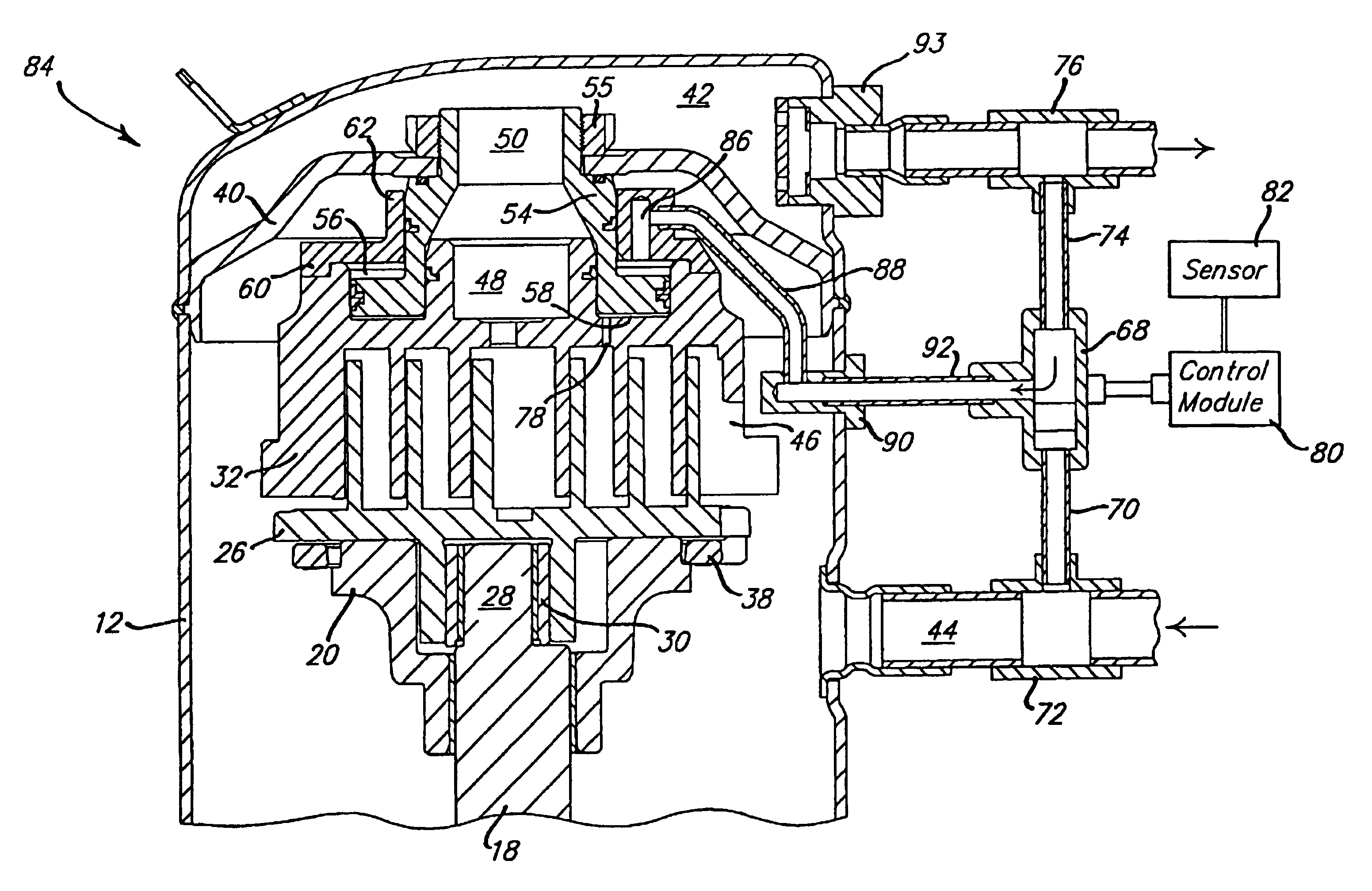
[0045]FIGS. 4 and 5 show another embodiment 94 of the present invention in which axial unloading separating pressure fluid is provided directly from the discharge gas exiting the compressor. In this embodiment, a tubular member 96 is suitably secured to partition member 40 and includes a radially outwardly extending flange 98 which is positioned in and separates cylindrical recess into upper and lower chambers 56 and 58. Tubular member 96 also defines passage 50 for directing compressed discharge gas from port 48 to discharge chamber 42. An axial extending bore 100 is provided in tubular member which opens outwardly through the upper end thereof and is adapted to receive a fluid conduit 102. Fluid conduit 102 extends outwardly through the top of shell 12 and is connected to solenoid valve 68. Solenoid valve also has fluid conduits 70 and 74 connected to respective suction and discharge lines 72, 76 and is controlled by control module 80 in response to signals from appropriate sensor...

embodiment 208

[0057]The embodiment 208 of FIG. 12 represents a combination of the axial unloading arrangement of FIG. 11 and the orbiting scroll biasing arrangement of FIG. 9 both described above. Accordingly, elements corresponding to like elements shown in and described with reference to FIGS. 9 and 11 are indicated by the same reference numbers. In this embodiment, the intermediate pressure axial biasing chamber 148b for the orbiting scroll is completely separate from the unloading discharge pressure biasing chamber defined by recess 184 and annular piston 186.

embodiment 210

[0058]In like manner, the embodiment 210 of FIG. 13 represents a combination of the intermediate pressure biasing arrangement of FIG. 8 described above and the axial unloading pressure biasing arrangement of FIG. 11. Accordingly, corresponding elements have been indicated by the same reference numbers used in these respective figures.


PUM


Abstract

A scroll-type machine is disclosed which is particularly well suited for use as a compressor in refrigeration and air conditioning systems and incorporates a unique arrangement for modulating the capacity thereof. In one group of embodiments the capacity of the scroll-type machine is modulated by relative axial movement between the scroll members so as to form a leakage path across the wrap tips and opposed end plates. In another group of embodiments, modulation is achieved by reducing the orbital radius of one of the scroll members to thereby form a leakage path across the flank surfaces of the wraps. In the second group, a plurality of pin members are moveable from a first and second positions. In a first position the plurality of pin members operably enable the scroll members to orbit and in a second position the pin members restrict the orbiting motion of the first scroll members. Both types of scroll separation may be accomplished in a time pulsed manner to thereby enable a full range of modulation with the duration of the loading and unloading periods being selected to maximize the efficiency of the overall system. A motor control arrangement is also disclosed which may be used with either of the modulation methods mentioned above to increase the efficiency of the motor during periods of reduced load. Additionally, either of the modulation arrangements mentioned above may be combined with a delayed suction form of capacity modulation with or without the motor control feature to thereby achieve better operating efficiency under certain conditions.

Description

[0001]This is a division of U.S. patent application Ser. No. 08 / 486,118, filed Jun. 7, 1995 U.S. Pat. No. 5,741,120.BACKGROUND AND SUMMARY OF THE INVENTION[0002]The present invention is related to capacity modulation of compressors and more particularly to capacity modulation of scroll-type compressors.[0003]Capacity modulation is often a desirable feature to incorporate in air conditioning and refrigeration compressors in order to better accommodate the wide range of loading to which the systems may be subjected. Many different approaches have been utilized for providing this capacity modulation feature ranging from controlling of the suction inlet to bypassing discharge gas back to the suction inlet. With scroll-type compressors, capacity modulation has often been accomplished via a delayed suction approach which comprises providing ports at various positions which, when opened, allow the compression chambers formed between the intermeshing scroll wraps to communicate with the suc...

Claims


Application Information

Patent Timeline
Patent Type & Authority Patents(United States)
IPC IPC(8): F04B49/02F01C1/063F01C1/02A47F3/04F04C18/02F04C27/00F04C28/00F04C28/02F04C28/06F04C28/08F04C28/18F04C28/22F04C28/26F04C28/28F25B1/04F25B5/02F25B41/04F25B41/06F25B49/00F25B49/02G05D1/08G05D23/19
CPCA47F3/04F04C27/005F04C28/00F04C28/02F04C28/06F04C28/08F04C28/22F04C28/265F04C28/28F25B1/04F25B49/022G05D1/0858G05D23/1909F04C18/0215Y02B30/72F04C23/008F04C2270/015F04C2270/86F25B49/005F25B2341/0653F25B2600/0261F25B2700/193F25B2700/1933F25B2700/2117F25B41/35Y02B30/70F04C18/02
Inventor BASS, MARKDOEPKER, ROY J.CAILLAT, JEAN-LUC M.WARNER, WAYNE R.
Owner EMERSON CLIMATE TECH INC
Why Eureka
Try Eureka