
Electrical box assembly

a technology of electrical boxes and components, applied in the direction of electrical apparatus casings/cabinets/drawers, gaseous cathodes, coupling device connections, etc., can solve the problems of compromising the function of the electrical box, the flange of the bracket cannot be properly seated, and the installation of electrical components to be subjected to contamination by cleaning fluid or other debris

Inactive Publication Date: 2010-09-14
THOMAS & BETTS INT INC
View PDF176 Cites 16 Cited by
  • Summary
  • Abstract
  • Description
  • Claims
  • Application Information

AI Technical Summary

Benefits of technology

[0006]It is an advantage of the present invention to provide an electrical box assembly that may be used both in and out of doors.
[0007]It is another advantage of the present invention to provide an electrical box having an adjustable face frame to permit secure mounting.
[0008]It is a further advantage of the present invention to provide a recessed electrical box having an adjustment device for permitting the face frame to be adjusted.
[0009]In the efficient attainment of these and other advantages, the present invention provides an electrical box assembly including a box having a base wall perimetrically bounded by a sidewall extending therefrom forming a housing adapted to receive an electrical component. The sidewall has an upper portion and a flange extending outwardly in a transverse direction from the upper portion. An electrical component attachment point is disposed adjacent the sidewall upper portion and adapted for securing an electrical component to the box. The flange is perimetrically bounded by a collar extending outwardly therefrom. The invention further includes a securement device supported on the box for securing the box to a support structure. Also provided is a frame which is in telescopic engagement with the collar and movable relative thereto. The frame has an abutment surface for abutting against a facing surface. An adjustment device is provided for moving the frame relative to the box and urging the abutment surface against the facing surface.
[0010]The adjustment mechanism extends between the frame and the box and includes a pair of threaded members threadedly engaged with the flange.
[0011]The electrical box assembly further includes a cover pivotally secured to the frame by a hinge and is movable between an open and closed position. The hinge includes at least one clip for permitting the cover to be selectively removed and attached to the frame. The cover includes at least one slot formed therein which is adapted to permit a power cord to extend therethrough when the cover is in the closed position.

Problems solved by technology

Indoor applications such as in a bathroom or industrial setting may also subject an installed electrical component to contamination from cleaning fluid or other debris.
If the housing is secured too far forward, then the bracket's flange will not seat properly against the wall surface allowing contamination to get between the cover and the wall.
If the housing is mounted too far toward the back of the stud, a gap may exist between the base and the front of the electrical component, thereby compromising the function of the electrical box.
There is no adjustability to accommodate for variation in the placement of the housing or the thickness of the wall covering.

Method used


Image

  • Electrical box assembly
  • Electrical box assembly
  • Electrical box assembly

Examples


Embodiment Construction

[0024]The present invention is directed to an electrical box assembly which may be used either in or out of doors. The electrical box assembly may be employed to house an electrical component such as an outlet, switch or voice / data connector. The electrical component may be recessed such that the front face of the electrical component is offset from a front face of a facing surface, such as wall board, surrounding the electrical box. The present invention provides adjustability in order to permit a secure installation which assists in preventing contamination from intruding upon the installation site or on the electrical component housed inside the electrical box.

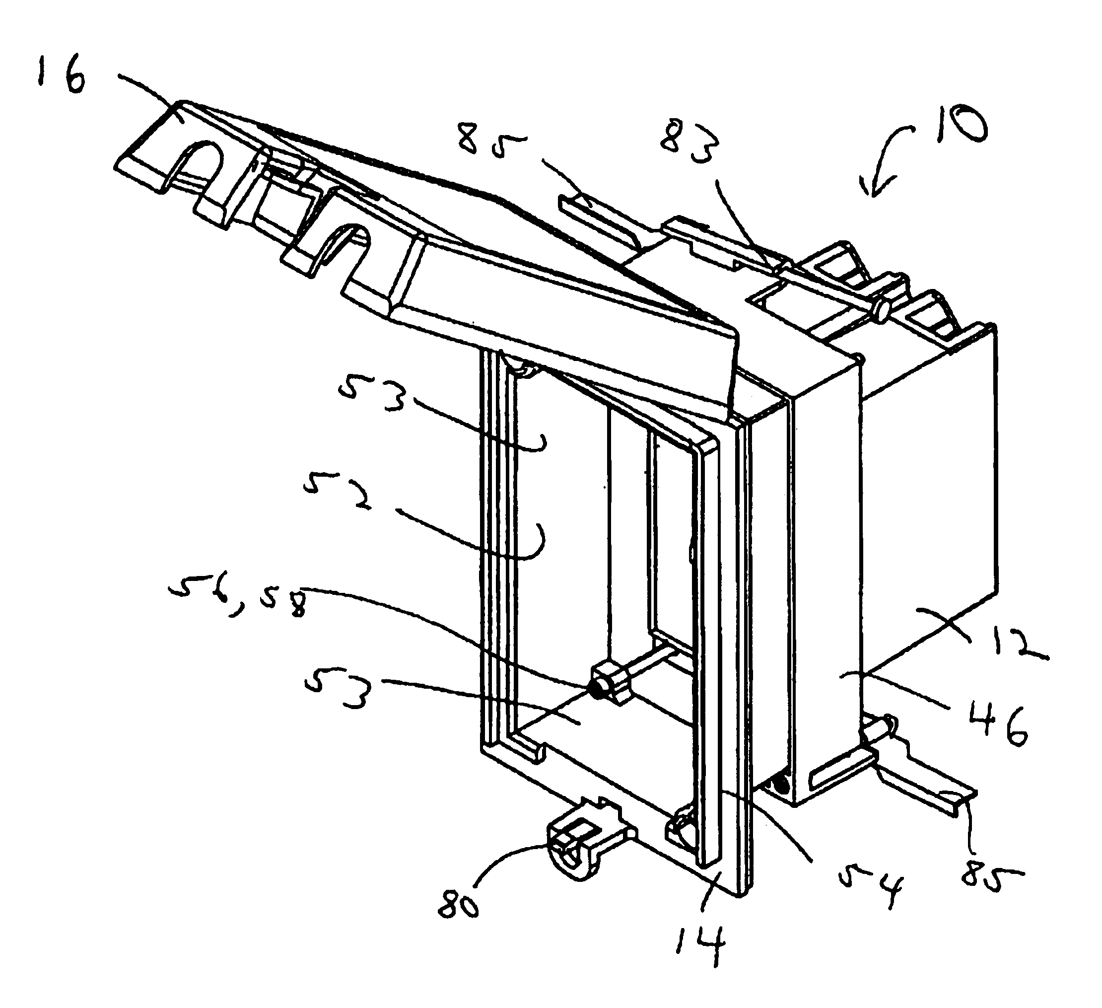
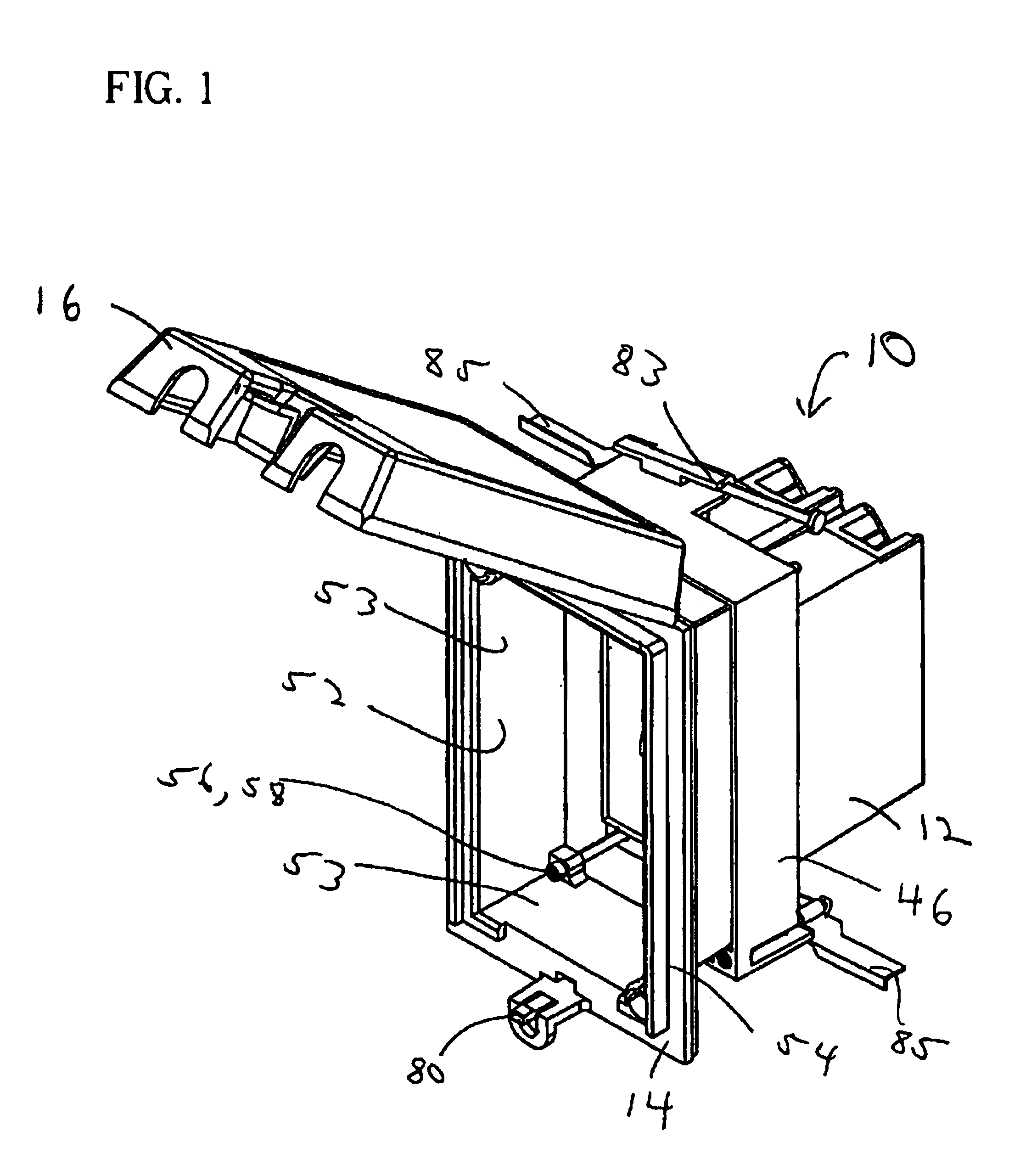
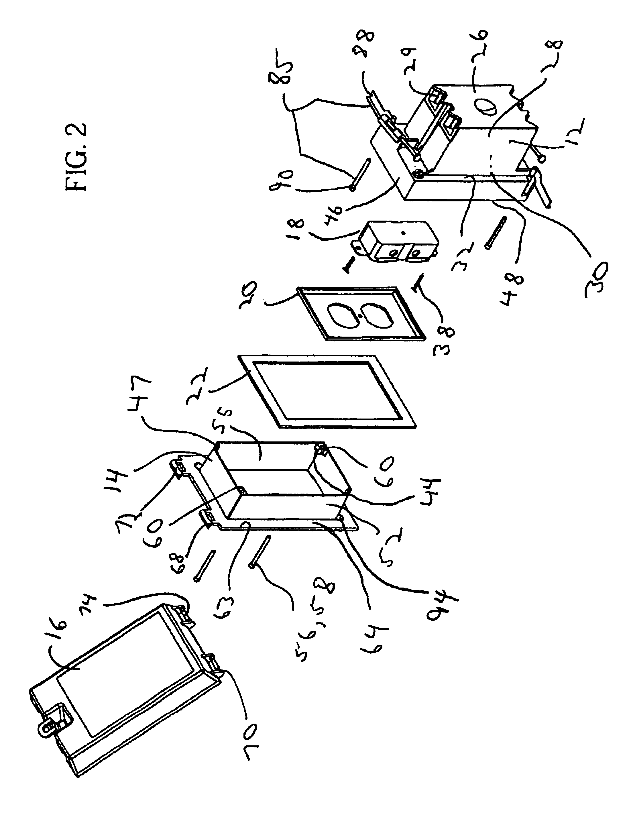
[0025]With reference to FIGS. 1-6, the present invention preferably includes a recessed electrical box assembly 10 having an electrical box 12, a face frame 14, and a cover 16. Electrical box 12 is adapted to secure an electrical component 18 such as a duplex outlet, switch or voice / data connector therein. Electrical compon...


PUM


Abstract

An electrical box assembly including a box having a base wall perimetrically bounded by a sidewall extending therefrom forming a housing adapted to receive an electrical component. The sidewall having an upper portion and a flange extending outwardly in a transverse direction from the upper portion. An electrical component attachment point is disposed adjacent the sidewall upper portion and adapted for securing an electrical component to the box. The flange is perimetrically bounded by a collar extending outwardly therefrom. A securement device disposed on the box for securing the box to a support structure is provided. A frame is further provided which is in telescopic engagement with the collar and movable relative thereto. The frame has an abutment surface for abutting against a facing surface. An adjustment device is provided for moving the frame relative to the box and urges the abutment surface against the facing surface.

Description

FIELD OF INVENTION[0001]The present invention relates to an electrical box assembly. More specifically, the present invention relates to a recessed electrical box assembly being adjustable in order to permit secure mounting.BACKGROUND OF THE INVENTION[0002]Electrical boxes provide a housing for electrical components such as outlets and switches when installed in the walls, ceilings or floors of buildings. Electrical boxes are typically secured to a support structure such as a wall stub and aligned with an opening in a covering material, such as wall board or siding. Boxes may be employed to house electrical components both in and out of doors.[0003]Outdoor applications typically utilize electrical boxes which can resist contamination such as water and dirt created by exposure to the elements. Indoor applications such as in a bathroom or industrial setting may also subject an installed electrical component to contamination from cleaning fluid or other debris. Typical outlet boxes inc...

Claims


Application Information

Patent Timeline
Patent Type & Authority Patents(United States)
IPC IPC(8): H02G3/08H02G3/12H02G3/14
CPCH02G3/088H02G3/121H02G3/14
Inventor DINH, CONG THANH
Owner THOMAS & BETTS INT INC
Learn More