Mower head with movable guard

a technology of rotary cutter and guard, which is applied in the field of mower heads, can solve the problems of reducing the cutting width of the blade, so as to achieve the effect of convenient access

Inactive Publication Date: 2011-02-08
CARTNER JACK O
View PDF16 Cites 1 Cited by
  • Summary
  • Abstract
  • Description
  • Claims
  • Application Information

AI Technical Summary

Benefits of technology

[0018]One advantage of the present invention is the provision of a new and improved mower head.
[0019]Another advantage of the present invention is the provision of a mower head with a guard which is pivotably attached to the deck and provides protection for a cutting blade of the mower head.
[0020]Still another advantage of the present invention is the provision of a mower head with a guard pivotably attached by a hinge at an angle with respect to two other sides of the deck of the mower head to allow more of the blade to be exposed and allow easier access to trees, shrubs, etc. for cutting.
[0021]Yet another advantage of the present invention is the provision of a mower head with a flap extending from the guard to protect the cutting blade when the guard is in its normal down position.
[0022]A further advantage of the present invention is the provision of a mower head with a guard which can be installed either in front of an angled main deck or above the main deck. If it is installed above the mower main deck, the front end of the main deck can be varied in shape.
[0023]Still other benefits and advantages of the invention will become apparent to those skilled in the art upon reading and understanding the following detailed description.

Problems solved by technology

Guarding the blades on a rotary cutter has always been a major problem.
Removing a straight front section of a rectangular or square mower housing, which acts as a guard, did not prove to be adequate.
This construction provides a very limited cutting swath for the blades.
This construction was disadvantageous because no shield extended downwardly to prevent the blades from throwing foreign objects when the guard is in its normal position.
Another problem with the prior art mower heads is that it is difficult to pass heavier brush and saplings below the shield into the cutting blade.
In areas along roadways and the like such devices are disadvantageous because people may be harmed by the cutting blade or objects thrown by the blade.

Method used


Image

  • Mower head with movable guard
  • Mower head with movable guard
  • Mower head with movable guard

Examples


Embodiment Construction

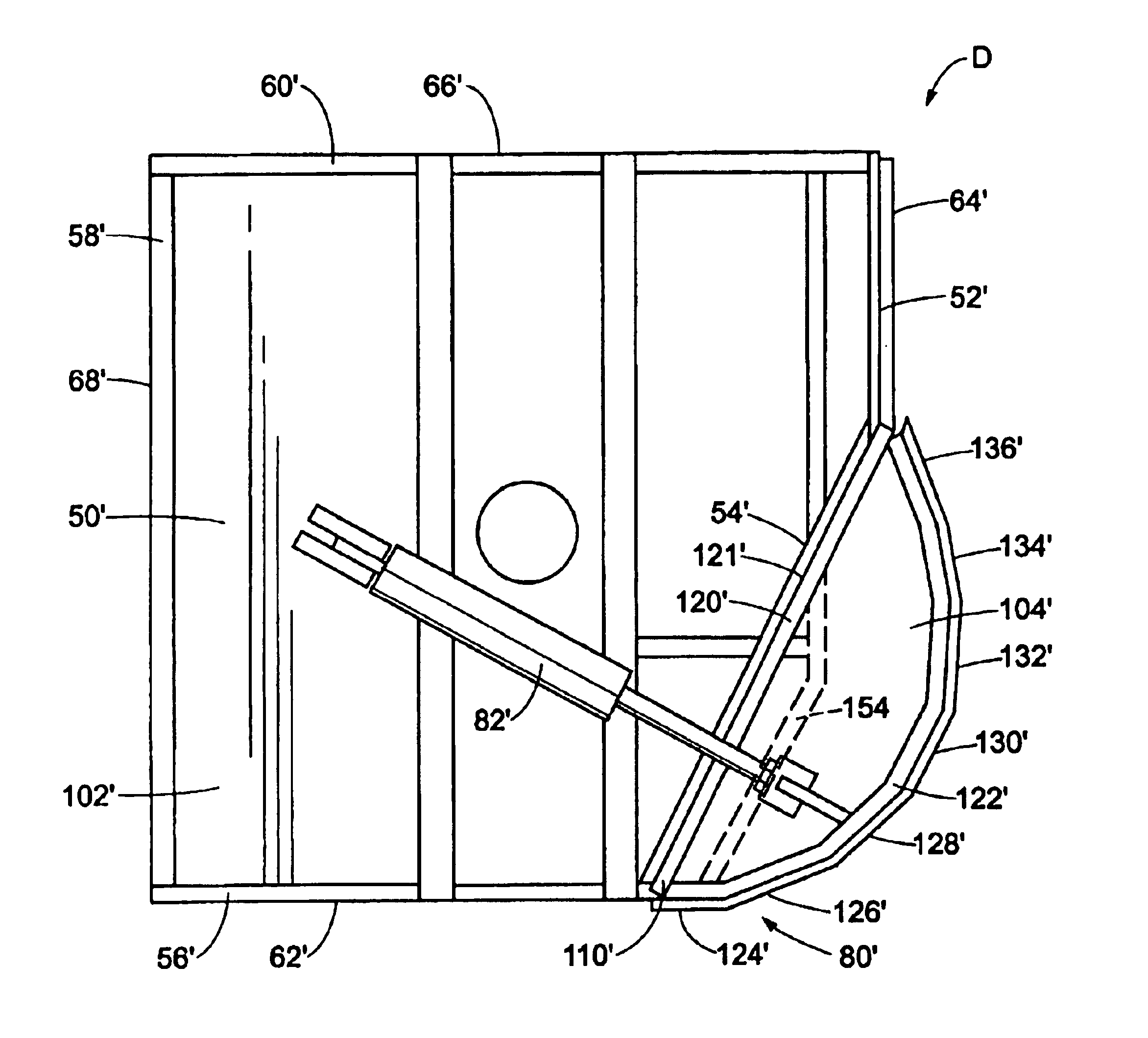
[0036]Referring now to the drawings, wherein the showings are for purposes of illustrating preferred embodiments of this invention only and not for purposes of limiting same, FIG. 3A shows a mower head C according to a first preferred embodiment of the present invention.

[0037]A mower includes a prime mover, such as a tractor (not shown), which is self-propelled to move at least in forward and rearward directions. An arm assembly (not shown) is operatively connected at one end with the prime mover and at the other end with the mower head. A positioning control means, such as a plurality of hydraulic cylinders, controls the position of the arm assembly relative to the prime mover and the mower head. In this manner, the position and orientation of the head is selectively variable. The arm assembly can be a boom assembly which includes at least two pivotally connected arms, one of which is pivotally connected with the prime mover and the other of which is pivotally connected with the mo...


PUM


Abstract

A mower head has a deck with at least three sides and at least one side wall depending from the deck. A cutting blade is rotatably mounted to the deck on an axis extending through the deck. The deck is disposed above and generally parallel to the blade. A guard assembly includes an actuating member mounted on the deck. The guard is attached to the actuating member and pivotally attached to the deck via a hinge along two sides of the deck. A flap depends from the guard. A flap also depends from one of the three sides of said deck. A top surface of the guard and a top surface of the deck can be located in the same plane. In a second embodiment, the guard includes a first wall having a plurality of angled sections which matingly interconnect with angled sections of one of the deck sides. In a third embodiment, the top surface of the guard and the top surface of the deck are located in different planes.

Description

BACKGROUND OF THE INVENTION[0001]The present invention relates to a mower head. More particularly, the present invention relates to a mower head with a movable guard.[0002]The invention finds particular application in conjunction with rotary brush and grass mowing and cutting apparatus for trimming highway medians and shoulders and will be described with particular reference thereto. It is to be appreciated, however, that the invention has other applications including clearing saplings, small trees, brush, grass, and the like.[0003]Heretofore, mowing heads have been mounted to tractors and other prime movers with various constructions including articulated arm assemblies and side arm assemblies. The mower heads commonly include one or a plurality of rotating cutting blades which are housed within a shield structure. The shield typically includes an upper deck and a skirt which extends from the upper deck below the rotary cutting blades along all but the forward side of the mower hea...

Claims


Application Information

Patent Timeline
Patent Type & Authority Patents(United States)
IPC IPC(8): A01D67/00
CPCA01D34/828
Inventor CARTNER, JACK O.
Owner CARTNER JACK O
Why Eureka
Try Eureka