
Method for setting cyclic shift considering frequency offset

a frequency offset and cyclic shift technology, applied in the field of sequences of wireless communication systems, can solve the problems of excessive performance or false alarm or throughput degradation, difficult to discriminate between sequences, etc., and achieve the effect of reducing the number of detection errors and false alarm rate, and minimizing the influence of frequency offs

Active Publication Date: 2019-10-22
LG ELECTRONICS INC
View PDF82 Cites 0 Cited by
  • Summary
  • Abstract
  • Description
  • Claims
  • Application Information

AI Technical Summary

Benefits of technology

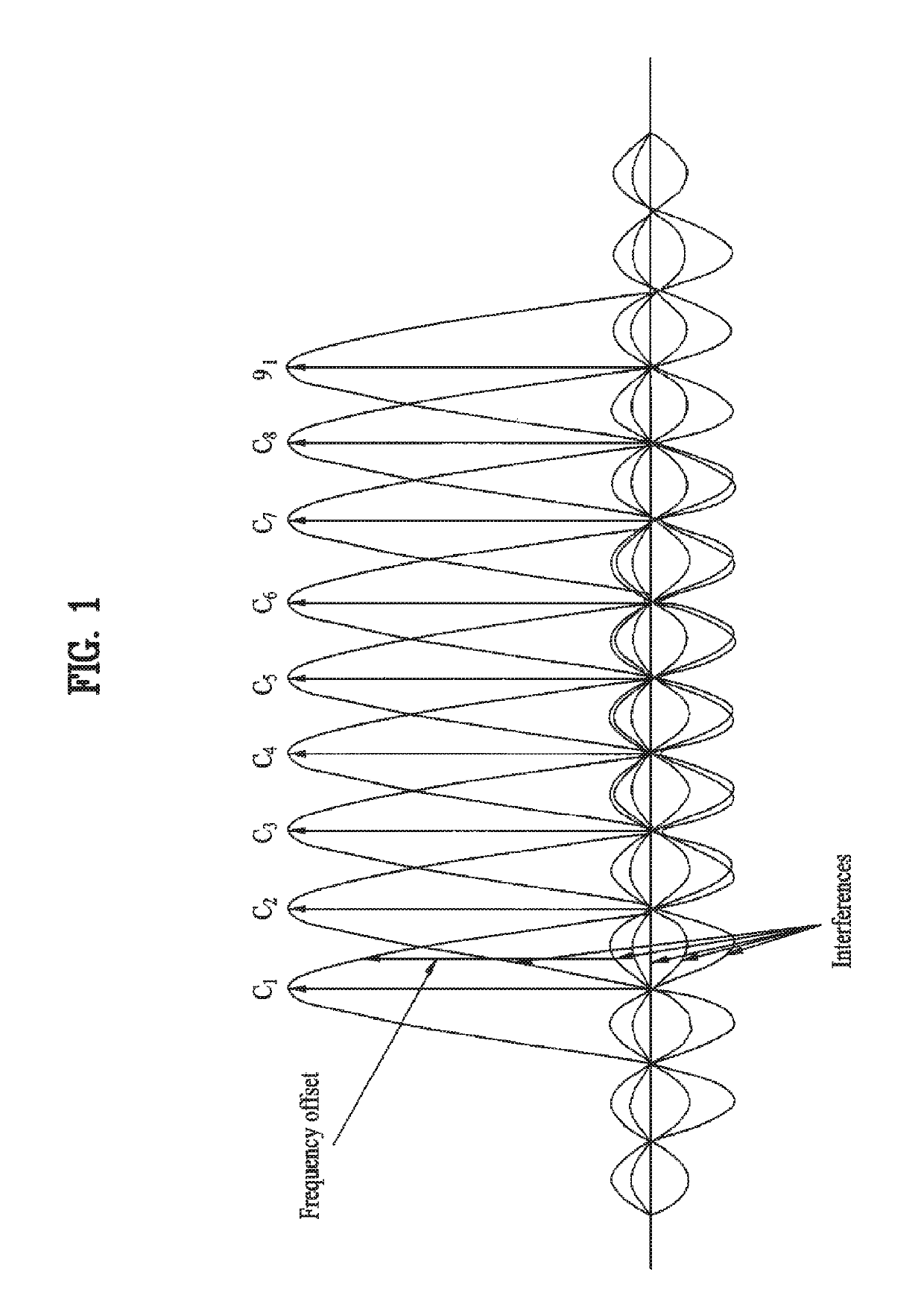
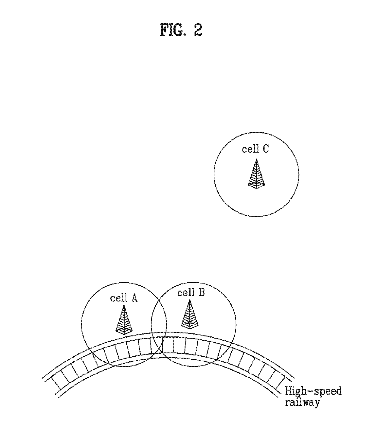
The present invention provides a method for preventing distortion of a sequence caused by frequency offset. This method can easily establish a cyclic shift interval to prevent the sequence deterioration, and can reduce the detection errors and false alarm rate. Additionally, if the cyclic shift sequence is allocated to a cell with frequency offset, it can minimize the impact of frequency offset on high-mobility cells.

Problems solved by technology

However, if the offset occurs in a frequency domain in the same manner as in the case where the CAZAC sequence is transmitted using the OFDM scheme, a performance or false alarm or throughput may be excessively deteriorated.
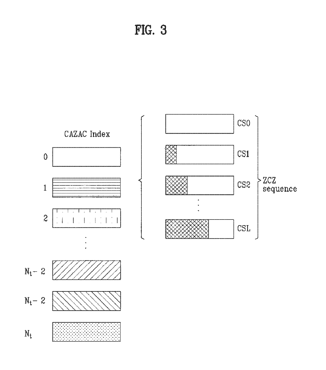
Specifically, if the cyclic shift (CS) is applied to the CAZAC sequence, the frequency offset or the timing offset excessively occurs, so that it is difficult to discriminate between sequences.

Method used


Image

  • Method for setting cyclic shift considering frequency offset
  • Method for setting cyclic shift considering frequency offset
  • Method for setting cyclic shift considering frequency offset

Examples


modified examples

[0301]A variety of modified examples applicable to the present invention will hereinafter be described.

[0302]Although the above-mentioned best mode has disclosed the specific case in which there is no restriction in the start point of the cyclic shift, the present invention can be applied to not only the above-mentioned case but also other restricted cases.

[0303]Not only the above-mentioned best mode, but also all the embodiments capable of being more generally applied to the present invention will hereinafter be described.

[0304]The position at which the alias occurs by the (+) Doppler frequency is denoted by the “+offset” position, and the position at the alias occurs by the (−) Doppler frequency is denoted by “−offset” position.

[0305]FIGS. 18 and 19 are conceptual diagrams illustrating a method for reducing the number of ZCZ preamble sequences due to an alias response in the case of Nzc=839, Ncs=100, and du−155 according to the present invention.

[0306]The cyclic shift of FIG. 18 c...


PUM


Abstract

A method for establishing a cyclic shift sequence to provide against the frequency offset is disclosed. The method calculates a distance between a channel response position of the sequence and an alias channel response position caused by a frequency offset, calculates the number of cyclic shifts per group according to the calculated distance, and establishes the cyclic shift (CS)-applying interval. This method easily establishes a cyclic shift (CS) interval at a specific location having no overlapping by considering a channel response of a reception (Rx) sequence and an alias location of this reception (Rx) sequence, although a reception (Rx) signal is shifted by a channel delay spreading or a propagation delay irrespective of categories of a domain generating a sequence, so that it can greatly reduce the number of the detection errors and the false alarm rate. And, if a sequence of the cyclic shift (CS) is allocated to a cell having a frequency offset of more than a predetermined level, the present invention can minimize the influence of a frequency offset on a high-mobility cell.

Description

CROSS-REFERENCE TO RELATED APPLICATIONS[0001]This application also claims the benefit of U.S. Provisional Application Ser. No. 60 / 883,754, filed on Jan. 5, 2007, U.S. Provisional Application Ser. No. 60 / 884,398, filed on Jan. 10, 2007, U.S. Provisional Application Ser. No. 60 / 915,096, filed on Apr. 30, 2007 and U.S. Provisional Application Ser. No. 60 / 941,562, filed on Jun. 1, 2007, the contents of which are hereby incorporated by reference herein in their entirety.[0002]This application is a reissue application of U.S. Pat. No. 7,792,212 B2, which issued on Sep. 7, 2010, from U.S. patent application Ser. No. 11 / 969,834, filed on Jan. 4, 2008, which claims the benefit of earlier filing date and right of priority to Korean Patent Application No. 10-2007-0011772, filed on Feb. 5, 2007 and Korean Patent Application No. 10-2007-00102563, filed on Oct. 11, 2007, the contents of which are all hereby incorporated by reference as if fully set forth herein in their entirety.BACKGROUND OF THE...

Claims


Application Information

Patent Timeline
IPC IPC(8): H04L27/04H04L1/00H04L27/26H04W56/00H04J13/00H04J13/22
CPCH04J13/0062H04J13/0074H04J13/22H04L27/2607H04L27/2613H04L27/2657H04L1/0023H04W56/00
Inventor LEE, HYUN WOONOH, MIN SEOKKWON, YEONG HYEONHAN, SEUNG HEEKIM, DONG CHEOLKWAK, JIN SAMVUJCIC, DRAGAN
Owner LG ELECTRONICS INC
Learn More