Fuel jet valve

A technology for fuel injection valves and valve seats, which is applied to fuel injection devices, injection devices, charging systems, etc., and can solve problems such as expensive sound insulation materials and increased manufacturing costs

Inactive Publication Date: 2007-09-26
HITACHI LTD
View PDF6 Cites 0 Cited by
  • Summary
  • Abstract
  • Description
  • Claims
  • Application Information

AI Technical Summary

Problems solved by technology

However, this solution not only requires the inherently expensive sound-deadening material, but also requires the process of installing a separate, different sound-deadening material on the fuel injection valve, further increasing the valve's manufacturing costs

Method used


Image

  • Fuel jet valve
  • Fuel jet valve
  • Fuel jet valve

Examples


Embodiment Construction

[0019] Referring to the drawings, a fuel injection valve for an internal combustion engine embodying the present invention will be described.

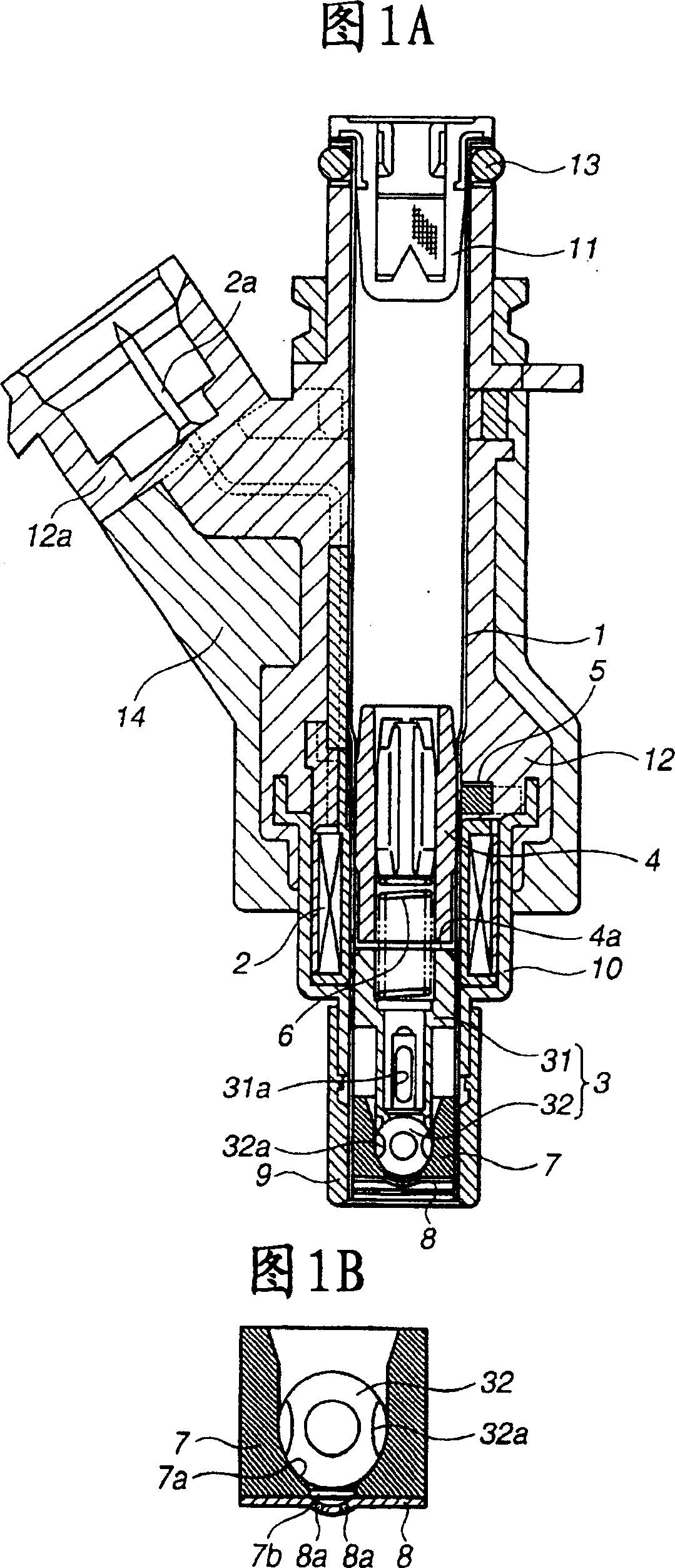
[0020] Referring to Figures 1A-2, a first embodiment of the present invention is shown. 1A and 1B, the fuel injection valve includes: a tubular housing 1, which is formed of a magnetic material such as metal; an electromagnetic coil or actuator 2, which is fixedly mounted on the outer edge of the housing 1; and a valve element 3 , which is axially and slidably arranged to pass through the housing 1, and includes a tubular holder 31 and a ball 32, which are integrally formed by welding. A fuel outlet 31 a is formed on a lower edge wall of the holder 31 . The ball 32 has flat surfaces 32 on the edges, which are obtained by machining.

[0021] A tubular spring housing 4 is fixedly mounted on the inner wall of the housing 1 above the valve element 3 (holder 31 ), as shown in FIG. 1A , while defining a predetermined gap therebetween. The...


PUM


Abstract

A fuel injection valve includes a soundproofing cover molded out of a rubber-containing soft resin and arranged on the outer periphery of a metal casing. Collision noises and vibrations are absorbed by the soundproofing cover, achieving excellent sound insulation. Moreover, the rubber-containing soft resin is lower in cost, and can be shaped by injection molding, resulting in a reduction in manufacturing cost of the valve.

Description

technical field [0001] The present invention generally relates to a fuel injection valve in an internal combustion engine and the like, and more particularly, the present invention relates to a technique for preventing bump noise and vibration during opening and closing of a valve element. Background technique [0002] As disclosed in JP-A-2002-534638 (=WO0040855), fuel injection valves in internal combustion engines and the like are typically constructed so that the valve element seated on the valve seat by the biasing force of the return spring is electromagnetically actuated. actuator to lift and open. [0003] The fuel injection valve generates bumping noise during the opening and closing of the valve element, more specifically, the bumping noise on the valve seat during the closing of the valve, and the stoppage of the valve element during the opening of the valve. The impact noise is generated on the device or its combination. These generated crash noises and vibrati...

Claims


Application Information

Patent Timeline
Patent Type & Authority Patents(China)
IPC IPC(8): F02M61/16F02M51/06F02M63/00F02M51/08F02M61/18
CPCF02M51/0682F02M61/1853Y10S239/90F02M51/0667
Inventor 斋藤贵博小屋敷秀彦
Owner HITACHI LTD
Why Eureka
Try Eureka