Automatic transmission mechanism of hydraulic motor

A hydraulic motor, automatic shifting technology, applied in steering mechanism, servo motor, variable displacement engine, etc., can solve problems such as poor handling feeling, poor acceleration feeling, and large deviation of shifting timing.

Active Publication Date: 2007-11-07
NABLESCO CORP
View PDF3 Cites 2 Cited by
  • Summary
  • Abstract
  • Description
  • Claims
  • Application Information

AI Technical Summary

Problems solved by technology

However, just by reducing the throttle valve, it is not possible to quickly shift from 1st speed to 2nd speed, and the acceleration feeling is poor, and the handling feeling is not good.
In addition, the gear shifting timings of the left and right hydraulic motors 4 and 5 are greatly deviated, and the straight forward performance of the construction machine is poor.

Method used


Image

  • Automatic transmission mechanism of hydraulic motor
  • Automatic transmission mechanism of hydraulic motor
  • Automatic transmission mechanism of hydraulic motor

Examples


Embodiment Construction

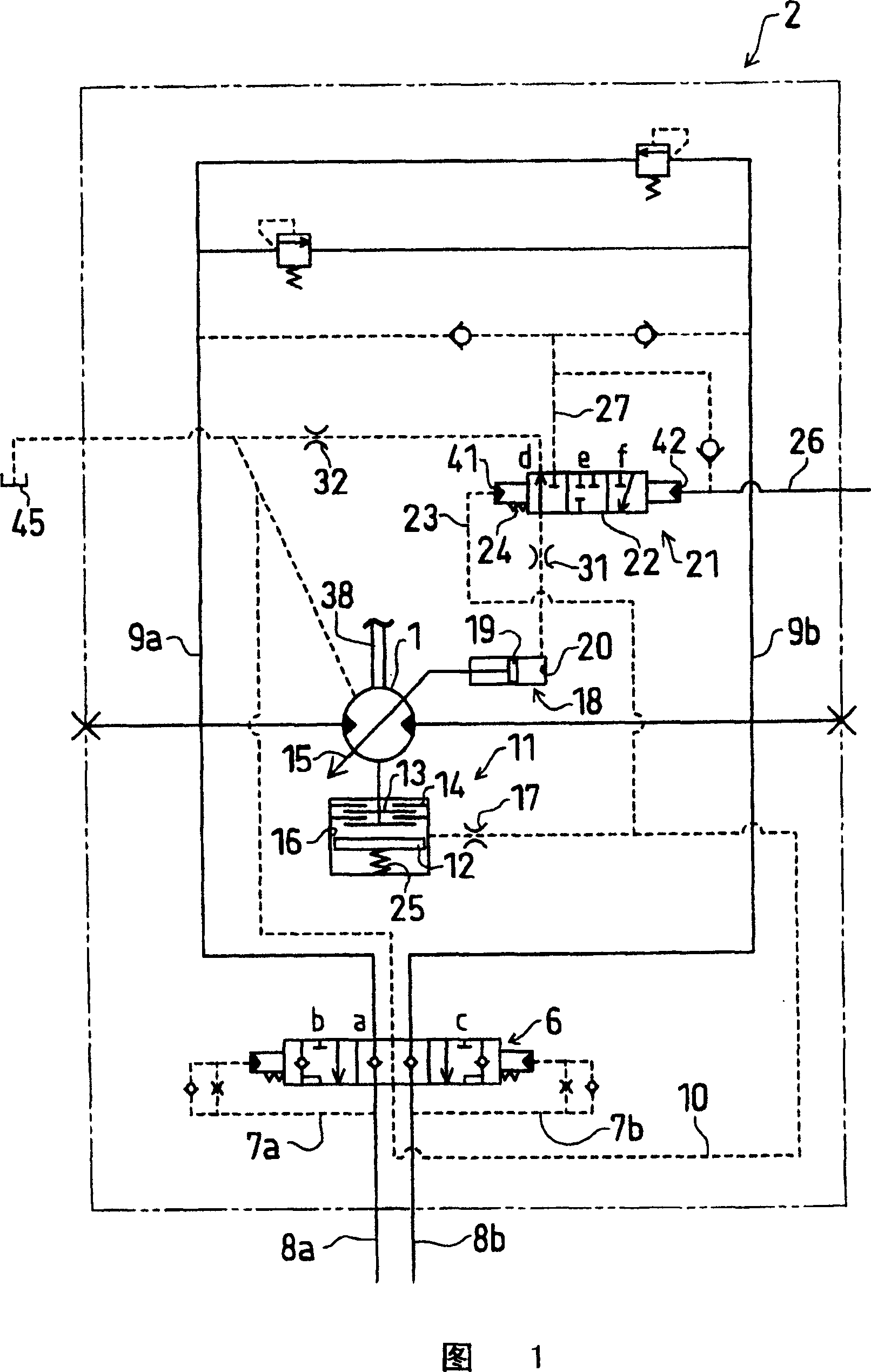
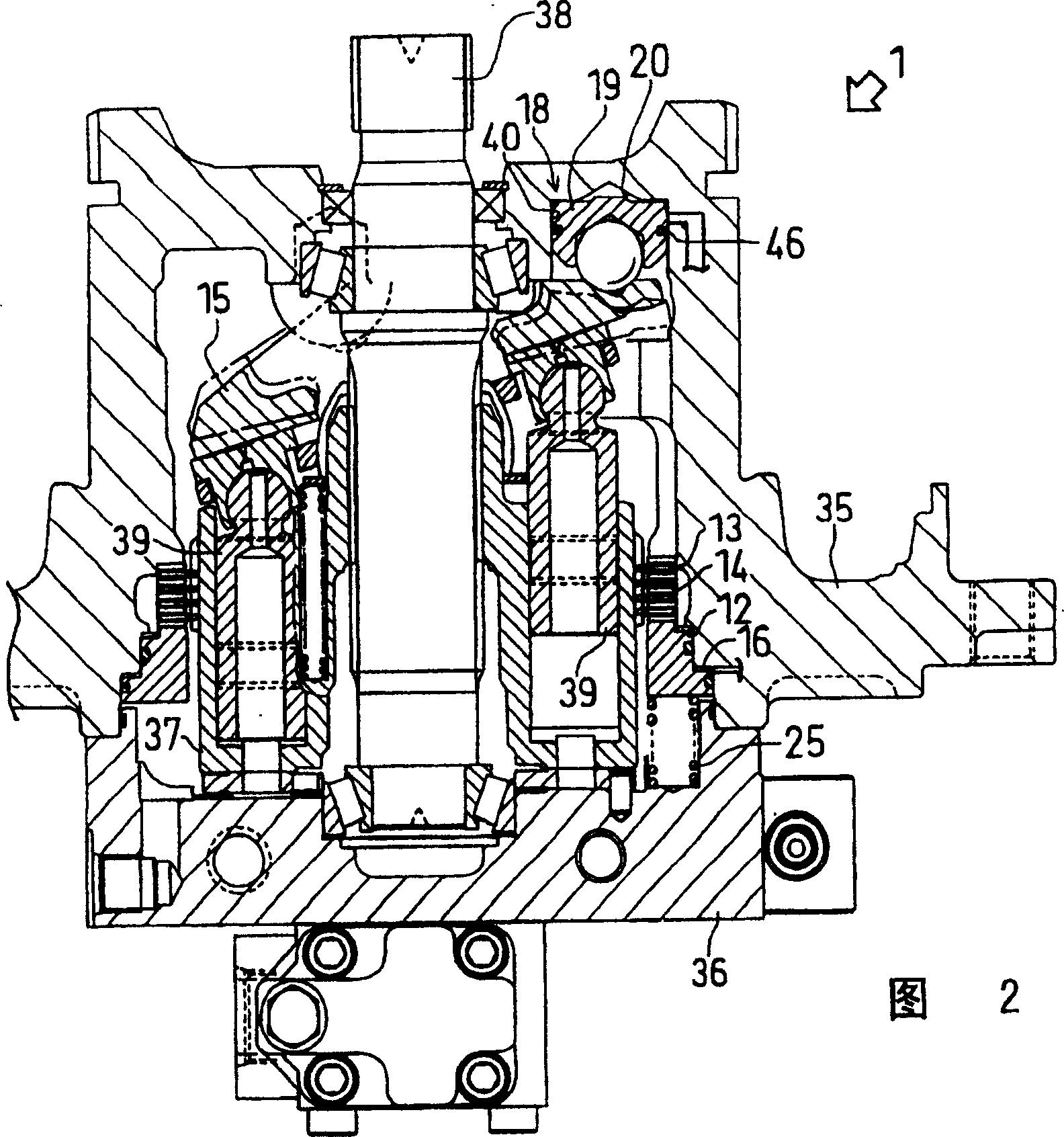
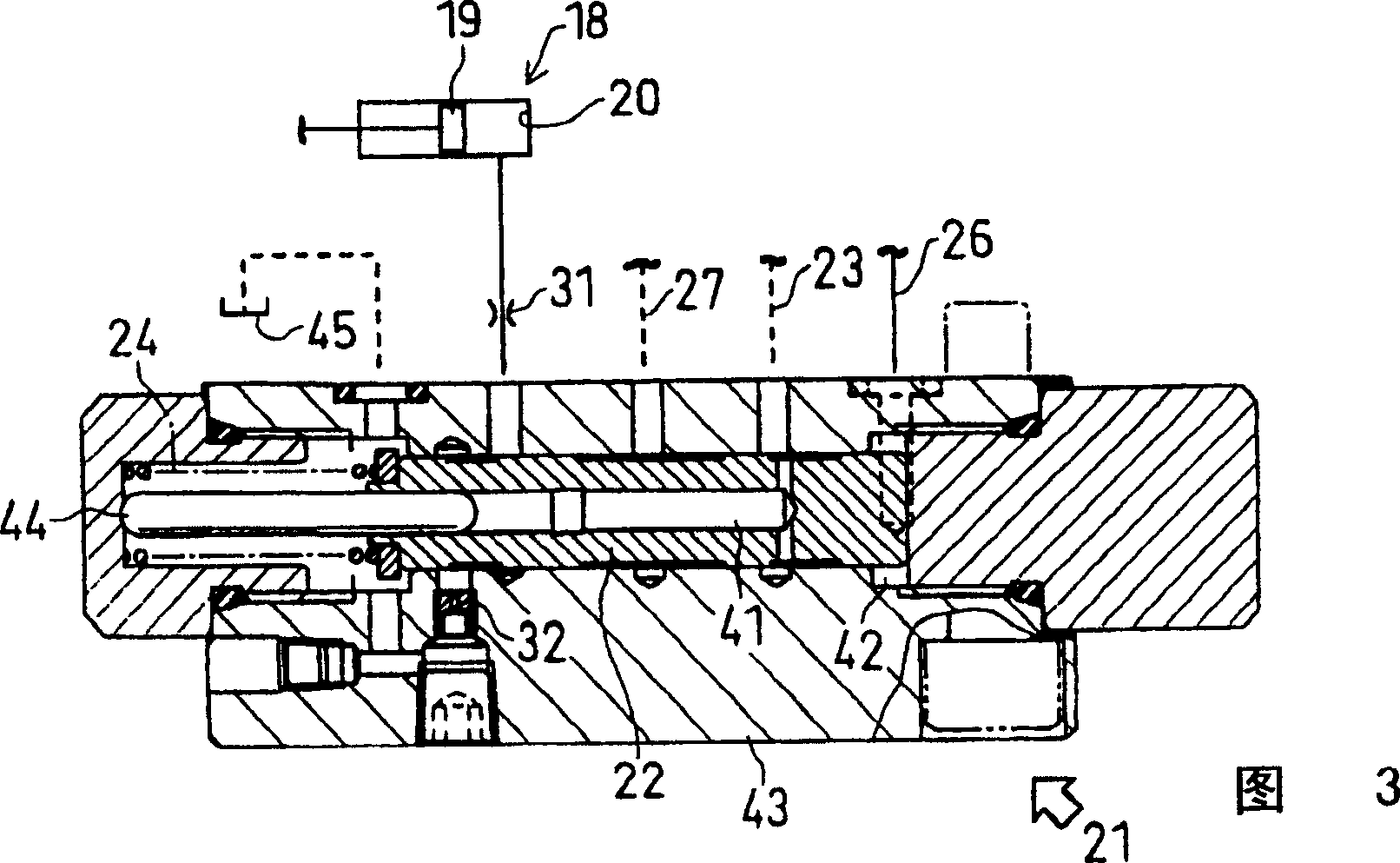
[0038] Embodiments of the present invention are described below. FIG. 1 is a hydraulic circuit diagram showing the overall configuration of an automatic transmission mechanism according to an embodiment of the present invention. Fig. 2 is a sectional view showing a specific configuration of the hydraulic motor. Fig. 3 is a cross-sectional view showing a specific configuration of a capacity switching valve. Fig. 4 is a graph showing the variation of the movable swash plate angle and the driving pressure when the present invention is configured to steer on the ground.

[0039] As shown in FIG. 1 , the hydraulic circuit 2 has a variable displacement hydraulic motor 1 . The hydraulic motor 1 is driven by the pressure oil supplied to the oil passages 9a and 9b, and applies driving force to the traveling axle of the construction machine. Oil supply and discharge passages 8a and 8b are provided for introducing pressurized oil into the aforementioned oil passages 9a and 9b, and the...


PUM


Abstract

To smoothly perform the turning with a good riding quality in an automatic transmission mechanism of a construction machine.A variable capacity type hydraulic motor 1 is shiftable to a second speed and a first speed. A capacity control cylinder 18 shifts the hydraulic motor 1 to the second speed when the pressure oil is supplied to a cylinder chamber 20, and to the first speed when the pressure oil is discharged. A capacity switching valve 21 is switchable between a supply position f for connecting the capacity control cylinder 18 with a hydraulic source and a discharge position d for connecting the capacity control cylinder 18 with a tank 45. A driving pressure passage 23 is formed to introduce a driving pressure of the hydraulic motor 1 to achieve the oil pressure for moving a valve element 22 of the capacity switch valve 21 to one side. When the construction machine is turned, a flow rate in supplying the pressure oil to the cylinder chamber 20 of the capacity control cylinder 18 is restricted by a first throttle 31, and a flow rate in discharging the pressure oil from the cylinder chamber 20 is restricted by the first throttle 31 and a second throttle 32.

Description

technical field [0001] The present invention relates to the technology of an automatic transmission mechanism of a hydraulic motor driving a traveling axle of a construction machine. Background technique [0002] As a transmission device of a hydraulically driven vehicle (for example, a construction machine such as a hydraulic excavator) whose axle is driven by a hydraulic motor, there is a device disclosed in Patent Document 1, for example. [0003] The structure of the aforementioned device is as shown in Fig. 1 of patent document 1, and its left and right sides have variable displacement hydraulic motors 4·5, and each hydraulic motor 4·5 has a function for changing and controlling its capacity (specifically, the inclination angle of the swash plate 11). ) capacity control pressure cylinder 12. The pressure chamber 14 of each displacement control cylinder 12 is connected to the control hydraulic pump 15 through a second switching valve (displacement switching valve) 21 . ...

Claims


Application Information

Patent Timeline
Patent Type & Authority Patents(China)
IPC IPC(8): F15B11/02F03C1/40E02F9/22B62D11/04F16H47/02F16H61/00F16H61/40F16H61/4035F16H61/4061F16H61/42F16H61/421F16H61/423
CPCF16H61/423F16H2061/0046
Inventor 佐竹辉彦奥藤秀和田所浩
Owner NABLESCO CORP
Why Eureka
Try Eureka