Suspended rotor MEMS micro-gyroscope utilizing static and charge relaxation to work

A suspension rotor and micro gyroscope technology, applied in the field of navigation control, can solve the problems of low control accuracy and sensitivity, complex structure, etc., and achieve the effect of improving suspension stiffness and effect, high precision and light weight

Inactive Publication Date: 2007-11-21
SHANGHAI JIAO TONG UNIV
View PDF4 Cites 0 Cited by
  • Summary
  • Abstract
  • Description
  • Claims
  • Application Information

AI Technical Summary

Problems solved by technology

[0004] This technology has the following disadvantages. Since the radial restoration control force of the above-mentioned comb electrodes on the rotor is much smaller than the suspension control force on the rotor axial direction, the control accuracy and sensitivity of the rotor radial direction of the gyroscope described in this patent It is lower than the axial one; due to the use of variable capacitors to make the rotor rotate at high speed, there must be separate electrodes or lands equivalent to electrodes on the stator and rotor, and the structure is complex

Method used


Image

  • Suspended rotor MEMS micro-gyroscope utilizing static and charge relaxation to work
  • Suspended rotor MEMS micro-gyroscope utilizing static and charge relaxation to work
  • Suspended rotor MEMS micro-gyroscope utilizing static and charge relaxation to work

Examples


Embodiment Construction

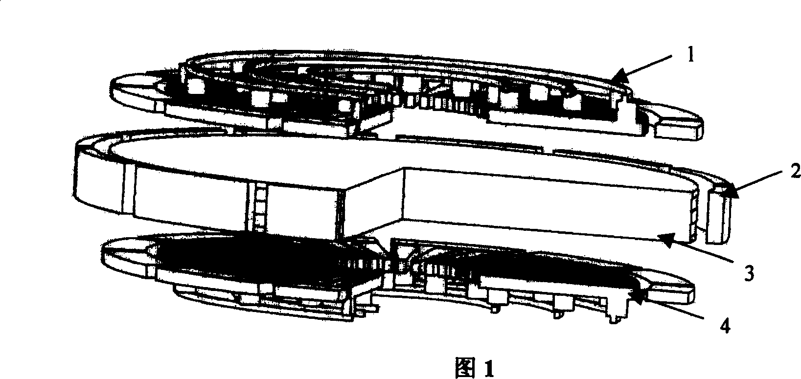
[0021] As shown in FIG. 1 , the present invention is composed of a stator 1 , a stator 4 , a rotor 3 and a peripheral structure 2 . The stator 1 is on the top, and the stator 4 is on the bottom. The stators 1 and 4 are connected through the peripheral structure 2 to form a cage structure, and the rotor 3 is placed in the middle of the cage structure.

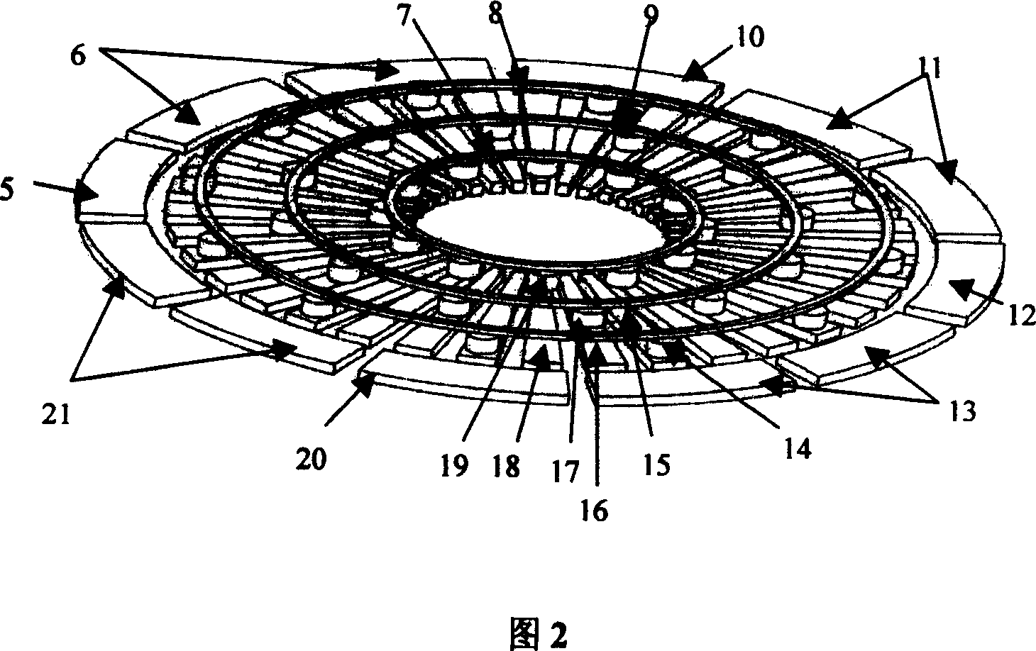
[0022] As shown in Figure 2, the structure of the stator 1 and the stator 4 consists of a square or rectangular cross section and a phase A conductive ring 8, a B phase conductive ring 9, a C phase conductive ring 7, and a plurality of A phase rotating electrodes. 15. Multiple A-phase electrode connecting columns 14, multiple B-phase rotating electrodes 16, multiple B-phase electrode connecting columns 17, multiple C-phase rotating electrodes 18, multiple C-phase electrode connecting columns 19, axial suspension electrodes 5 , 10, 12, 20 and axial detection electrode pairs 6, 11, 13, 21 constitute. A-phase conductive ring 8, B-...


PUM


Abstract

This invention relates to a floating rotor MEMS micro-gyroscope by use of static electricity and charge relaxation and can be applied in navigational control fields, such as satellite and automobile. This invention comprises double stator, periphery structures and rotor. The double stator is located up-and-down and forms a basket structure by connecting with periphery structures. The rotor is fixed in the center of the basket structure. And the periphery structures is around the rotor and comprises radial suspension electrode and radial detecting electrode pair that lies between radial suspension electrodes. This invention realizes the suspension stability and position detecting of the rotor by setting axial and radial detecting and suspension electrode.

Description

technical field [0001] The invention relates to a MEMS (micro-electromechanical system) micro-gyroscope, in particular to a suspended rotor MEMS micro-gyroscope which utilizes static electricity and charge relaxation to work, and is used in the navigation control fields of satellites and automobiles. Background technique [0002] MEMS devices have the characteristics of miniaturization, low cost, low energy consumption, and mass production. In recent years, scholars and engineers from various countries have tried to design and manufacture suspended rotor MEMS micro gyroscopes. [0003] After literature search, it was found that the US patent "acceleration-detecting type gyro and manufacturing method thereof" (patent No. 5920983) mentions an electrostatic micro-rotor that can simultaneously measure two-axis angular velocity and three-axis acceleration. The gyroscope adopts a glass-silicon-glass bonding structure, and the stator is formed by making electrodes on the glass, and...

Claims


Application Information

Patent Timeline
Patent Type & Authority Patents(China)
IPC IPC(8): G01C19/24
Inventor 张卫平陈文元赵小林段永瑞崔峰
Owner SHANGHAI JIAO TONG UNIV
Why Eureka
Try Eureka