Stand by control circuit of TV set and TV set with said stand by control circuit

A technology of a control circuit and a switch control circuit, applied in the field of televisions, can solve the problems of impracticality of external circuits and high decoding cost, and achieve the effects of reducing standby power consumption, power consumption and no-load power consumption.

Inactive Publication Date: 2007-11-28
SHENZHEN SKYWORTH RGB ELECTRONICS CO LTD
View PDF7 Cites 1 Cited by
  • Summary
  • Abstract
  • Description
  • Claims
  • Application Information

AI Technical Summary

Problems solved by technology

The best way to solve the interference problem is to add a dedicated decoder to the external circuit to identify the infrared signal used to control the external circuit, but the cost of decoding is too high, making the external circuit impractical

Method used


Image

  • Stand by control circuit of TV set and TV set with said stand by control circuit

Examples


Embodiment 1

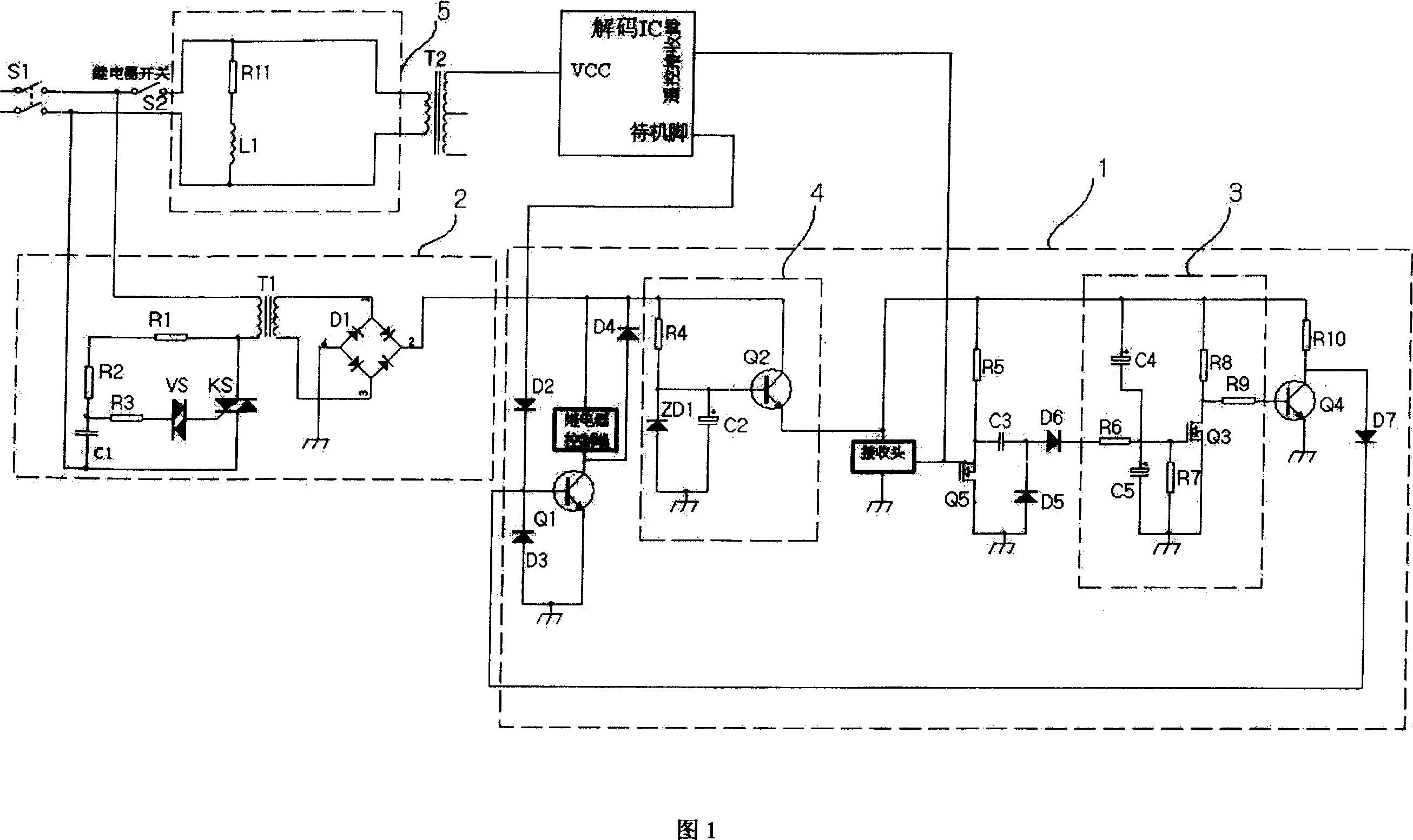
[0026] As shown in Figure 1.

[0027] A TV standby control circuit, comprising an electromagnetic relay and a switch control circuit 1 for controlling the electromagnetic relay, the switch S2 of the electromagnetic relay is connected between the TV power supply and the TV degaussing circuit 5, the switch control circuit 1 controls the electromagnetic relay, And the TV power switch is controlled by the relay to achieve the purpose of standby and starting. The relay is off when the power goes out, the TV is not powered and does not work. When the relay is energized, it closes, and the TV resumes power supply and works normally. The TV standby control circuit also includes a power supply circuit 2 connected between the TV power supply and the relay switch S2, for converting the AC power into a DC power supply to supply power to the switch control circuit 1.

[0028] The switch control circuit 1 includes a remote control receiving head connected to the remote control receiving p...

Embodiment 2

[0040] A television set with a standby control circuit, which is the same as that described in Embodiment 1.


PUM


Abstract

Present invention discloses TV set standby control circuit. It contains electronic switch and on-off control circuit, wherein said on-off control circuit connected with decode chip of TV set CPU, in receiving remote controller infrared signal to make electronic switch conduction a period of time, in this period of time, CPU decode chip identifying whether the next received infrared signal being right switching on signal, if it is not then the on-off control circuit controlling electronic switch being off. Present invention also discloses TV set having said standby control circuit. Present invention realizes micro - power consumption standby (only 500 mW), and can prevent effectively TV set TV set incorrect operation resulted by interference signal.

Description

technical field [0001] The invention relates to a control circuit inside a TV set and a TV set, in particular to a standby control circuit inside the TV set and a TV set with the standby control circuit. Background technique [0002] The TV sets produced by various manufacturers now use DC standby as the standby mode. The way of the DC standby is to let the line circuit stop working during standby, so that the color tube has no output, but many other circuits except the line circuit are still in the working state and consume power. At this time, the standby power consumption is about 5W. In this way, if the standby time is long, a lot of electric energy is often wasted. [0003] Before the present invention, a method of using an external circuit to control the on and off of the TV power supply to reduce the standby power consumption has also appeared in the industry, but a big problem encountered when using this method is that the external Signal interference problem. Bec...

Claims


Application Information

Patent Timeline
Patent Type & Authority Patents(China)
IPC IPC(8): H04N5/63
Inventor 吴沛杨军治
Owner SHENZHEN SKYWORTH RGB ELECTRONICS CO LTD
Why Eureka
Try Eureka