Power supply system based on bus/current collector

A technology of power supply system and bus bar, which is applied in the direction of power lines, rail joints, roads, etc., and can solve problems affecting the continuity of current guidance

Inactive Publication Date: 2007-12-05
SIEMENS AG
View PDF8 Cites 0 Cited by
  • Summary
  • Abstract
  • Description
  • Claims
  • Application Information

AI Technical Summary

Problems solved by technology

However, the continuity of the current conduction is thereby affected, however, only a mitigation of the problem can be achieved here and not a satisfactory solution

Method used


Image

  • Power supply system based on bus/current collector
  • Power supply system based on bus/current collector
  • Power supply system based on bus/current collector

Examples


Embodiment Construction

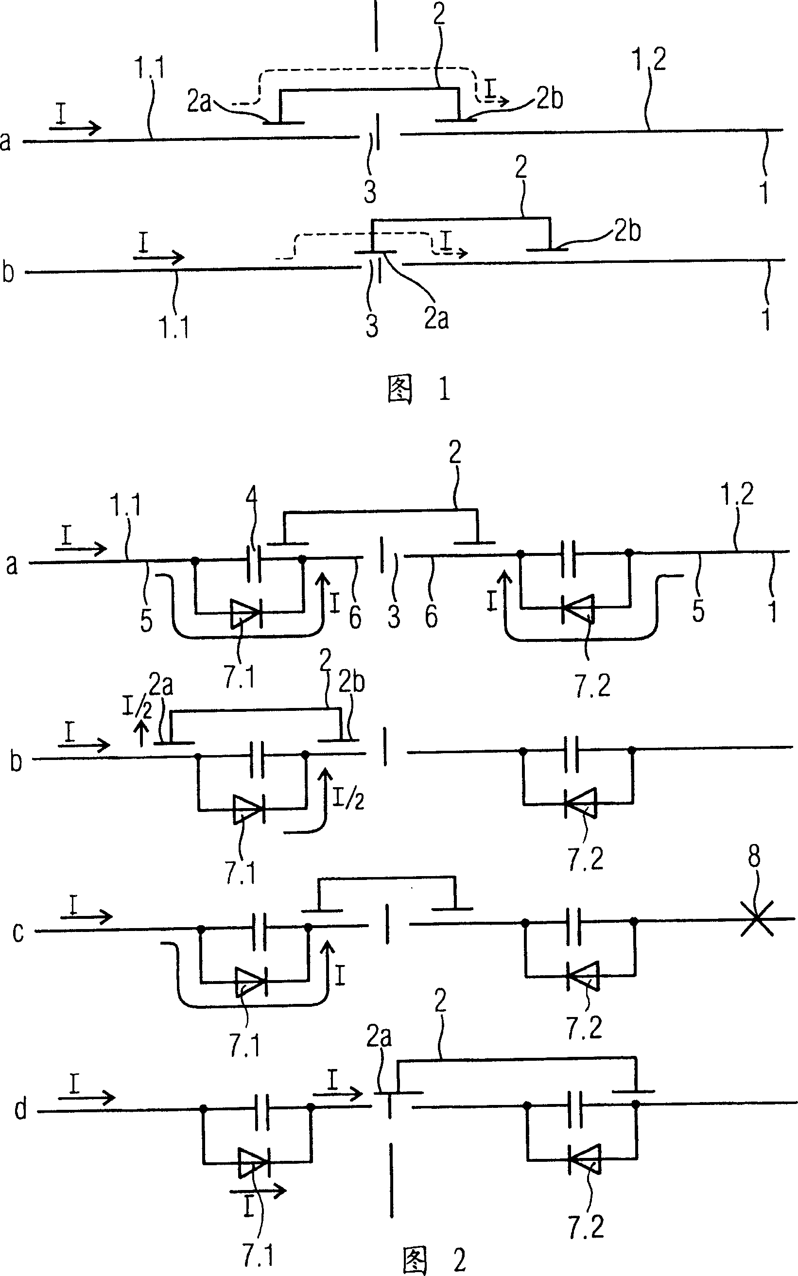
[0013] FIG. 1 shows a busbar 1 of conventional design for two different positions a and b of a current collector 2 which is connected to a power supply unit of a vehicle. The busbar 1 is subdivided into feeder segments, of which two segments 1.1 and 1.2 are partially shown. There is a separation point 3 between the feed sections 1.1 and 1.2. According to a in the figure, the current collector 2 with the contact points 2 a and 2 b bridges the separation point 3 . The contact points 2a and 2b may be sliding contact points. Obviously, in this position a, almost all the current I flows from the feeder segment 1.1 through the collector 2 to the subsequent feeder segment 1.2. This current is shown by dashed lines. In the position b, where the contact point 2 a of the current collector 2 is at the separation point 3 , the current I flows through this contact point 2 a. Such a current indicated by a dotted line is undesirable and has hitherto only been insufficiently suppressed by...


PUM


Abstract

The supply system based on bus / current collector has the current rail (1) provided with successive energy supply sections (1.1,1.2) which can be coupled together or separated from one another, with a cooperating current take-off (2) used for supplying an energy supply unit onboard a vehicle. Each energy supply section (1.1,1.2) has a current rail end piece (6) mechanically coupled via an insulation piece (4) with a current rail centre piece (5), with briding diodes (7.1,7.2) across the insulation pieces (4) of the adjacent energy supply sections having the same poles facing the separation gap (3) between the latter (6).

Description

technical field [0001] The invention relates to a power supply system based on a busbar / collector, wherein the busbar has separate or coupled feed sections and at least one collector supplies current to a feed unit of the vehicle. A busbar is understood here to mean an electrical power supply system which is divided into feeder sections and supplies the various traffic systems with direct current, in particular likewise the upper conductor rails. Some notable problems have hitherto arisen in such power supply systems due to undesired currents and arcing. Background technique [0002] For a vehicle whose each polarity is supplied via one or more electrically connected and spatially separated current collectors, this relates in particular to so-called transverse currents through relays and / or the vehicle. The transverse current is driven by the voltage difference of the supply segments adjacent to one another from a separation point. [0003] On a current collector, undesire...

Claims


Application Information

Patent Timeline
Patent Type & Authority Patents(China)
IPC IPC(8): B60M3/04B60M1/18E01B11/54B60M5/00
CPCB60M5/00B60M1/18
Inventor 冈瑟·巴迪格乔尔格·莱普富尔沃尔夫冈·斯佩思福尔克-亨纳·瓦格纳
Owner SIEMENS AG
Why Eureka
Try Eureka