Bushhammer

A chisel machine and frame technology, which is applied in the field of chisel machines, can solve problems such as the inability to fundamentally eliminate the hazards of concrete surface slurry, the difficulty in meeting the requirements for smooth concrete surface rough treatment, and the inability to guarantee the quality of building construction. Achieve the effect of good chiseling quality, lighten heavy manual labor, and strong randomness

Inactive Publication Date: 2007-12-05
李树龙
View PDF5 Cites 0 Cited by
  • Summary
  • Abstract
  • Description
  • Claims
  • Application Information

AI Technical Summary

Problems solved by technology

[0002] In the construction of construction projects, especially in high and low-speed highways, bridges, overpasses, culverts, and slab projects, it is often necessary to pour again on the smooth surface of concrete products that have been poured. In order to improve the attachment of new and old concrete surfaces Focus on, first of all, gouging the smooth surface of the concrete that has been poured. In layman's terms, it is to roughen the smooth surface of the concrete to improve the grip of the concrete surface, especially in recent years. The formwork is easy to form the surface slurry, and the surface of the concrete product is smoother; at present, in the construction industry, the rough treatment of the concrete surface is still done manually, and the operator usually uses a steel drill and a hand hammer to grind the concrete surface. The surface is hammered and chiseled, and pits of different sizes and sizes are chiseled to make the surface rough. Each person can only chisel a few square meters per day. The technology is backward, dust pollution, labor intensity is high, production efficiency is low, and the quality of chiseling Irregularity, it is difficult to meet the rough treatment requirements for the smooth surface of the concrete; in order to reduce the weight of benzene, manual labor or chiseling with picks or sandblasting, but the effect is not great; Hair, but brushing cannot fundamentally eliminate the hazards caused by the concrete surface slurry, nor can it guarantee the quality of construction

Method used


Image

  • Bushhammer
  • Bushhammer

Examples


Embodiment Construction

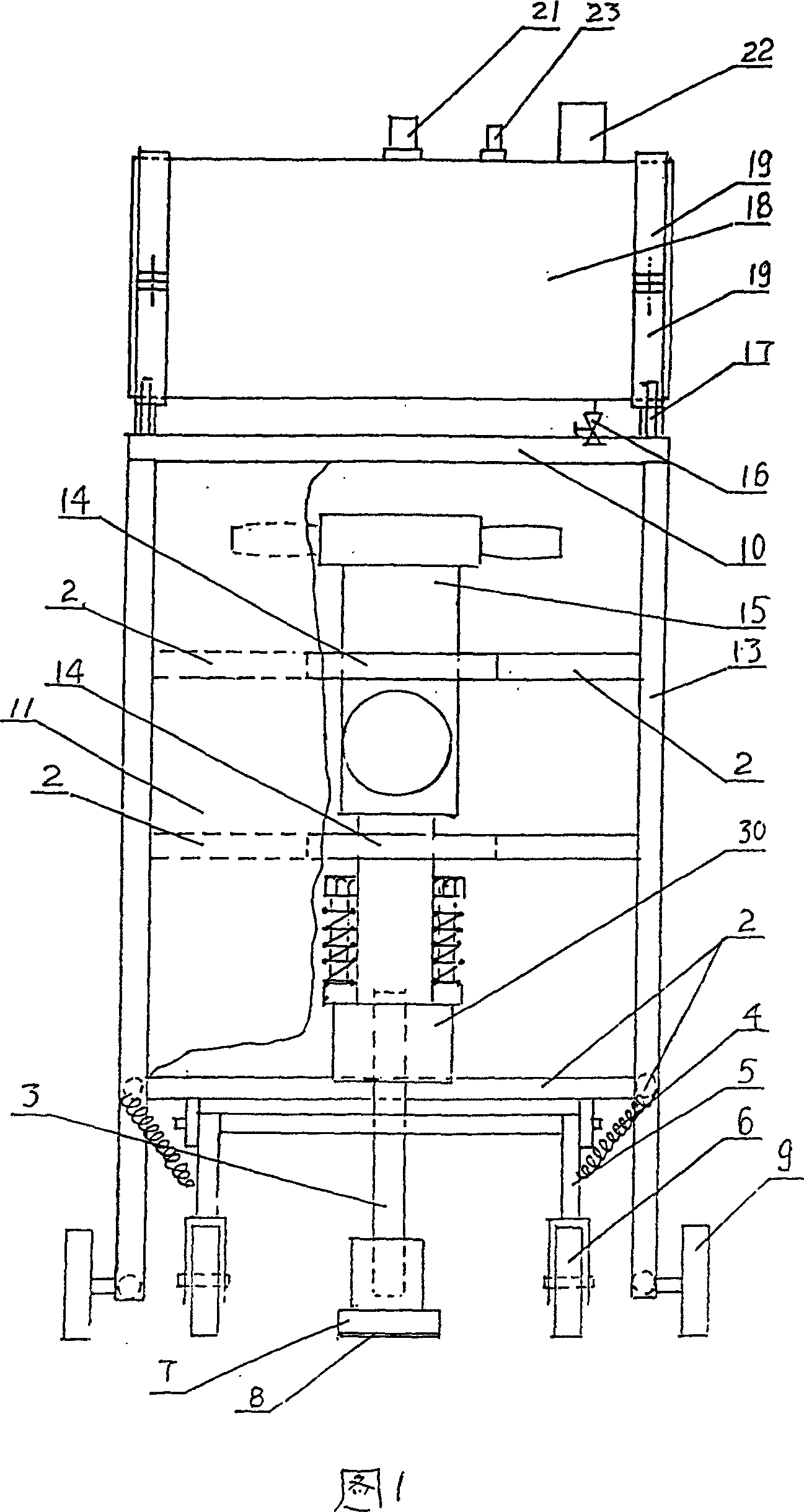
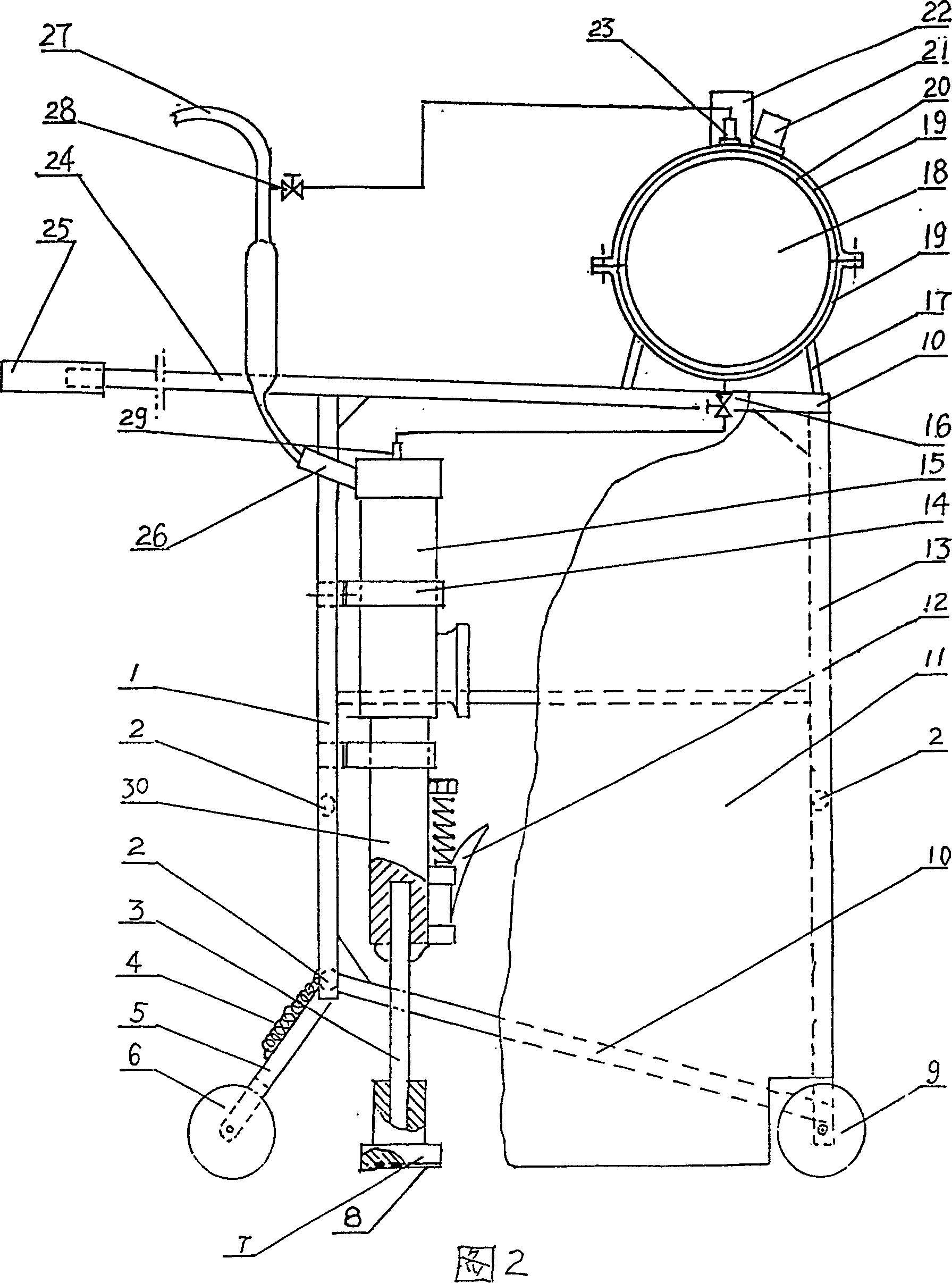
[0015] Shown in Fig. 1, 2 is one of embodiment of the present invention, and the upper and lower parts of its chisel head 7 are circular, and the cemented carbide grain block in the cemented carbide layer 8 is the chisel machine that strip shape is evenly distributed, Its structure includes: frame, dust screen curtain 11, pneumatic drill body 15, chisel head device, air pressure cooling water tank 18, hand-push damping handle 24, universal wheel 6 landing gear, front roller 9, consists of left, The front and rear poles 13,1, crossbeam 2, top and bottom beams 10 of the right are assembled to form a square frame, and the front, rear, left and right sides of the frame are connected with dust-proof screens 11 made of thin iron plates, The upper and lower clips 14 in the frame are fixed to the pneumatic drill body 15 on the rear side beam 2, the drill pipe connection sleeve 30 of the pneumatic drill body 15 faces downward and is perpendicular to the ground, and the drill pipe connec...


PUM


Abstract

The invention relates to a new chipper machine which features that: square framework made up of vertical pole and cross beam covering with dust shed, air driller is fixed on back beam by bar clasp, driller pole connecting sleeve is perpendicular to ground and inserted with chipper pole, chipper plate, chipper plate made of hardening alloy layer of which the alloy layer surface contacts with ground, horizontal pneumatic cooling water tank is fixed on the top of framework by bar clasp with water inlet port on the top, air inlet port, safety valve, and water supply valve on the bottom stretching to back of framework top beam forming a handle, rubber damping tube is set at the end of the handle, fore rolling wheel is installed at the base of fore vertical pole in correspond to a universal wheel landing chassis hinged on back vertical pole consisting of landing chassis, spring, support pork and universal wheel. The invention is of rational structure, light and high efficiency without mill dust pollution and very convenience.

Description

technical field [0001] The invention relates to a roughening device for concrete surfaces in construction machinery, and is particularly suitable for a kind of roughening machine which replaces heavy manual work with machinery. Background technique [0002] In the construction of construction projects, especially in high and low-speed highways, bridges, overpasses, culverts, and slab projects, it is often necessary to pour again on the smooth surface of concrete products that have been poured. In order to improve the attachment of new and old concrete surfaces Focus on, first of all, gouging the smooth surface of the concrete that has been poured. In layman's terms, it is to roughen the smooth surface of the concrete to improve the grip of the concrete surface, especially in recent years. The formwork is easy to form the surface slurry, and the surface of the concrete product is smoother; at present, in the construction industry, the rough treatment of the concrete surface i...

Claims


Application Information

Patent Timeline
Patent Type & Authority Patents(China)
IPC IPC(8): E01C23/085
Inventor 李树龙
Owner 李树龙
Why Eureka
Try Eureka