Horizontal column type heat exchanger exterior dirt three-phase fluidization in-situ cleaning process

A technology of horizontal tubes and heat exchangers, which is applied in the direction of cleaning heat transfer devices, non-rotating equipment cleaning, lighting and heating equipment, etc.

Inactive Publication Date: 2007-12-12
株洲工学院帅科机械清洗研究所
View PDF7 Cites 0 Cited by
  • Summary
  • Abstract
  • Description
  • Claims
  • Application Information

AI Technical Summary

Problems solved by technology

[0003] The patent of this invention aims to solve the problem of online rapid cleaning of dirt outside the tubes of this horizontal tube heat exchanger, and proposes a horizontal tube heat exchanger with fluidized online cleaning of the shell side

Method used


Image

  • Horizontal column type heat exchanger exterior dirt three-phase fluidization in-situ cleaning process
  • Horizontal column type heat exchanger exterior dirt three-phase fluidization in-situ cleaning process
  • Horizontal column type heat exchanger exterior dirt three-phase fluidization in-situ cleaning process

Examples


Embodiment Construction

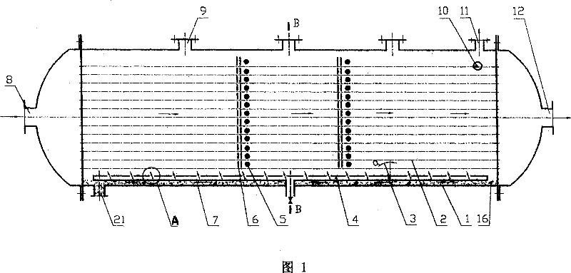
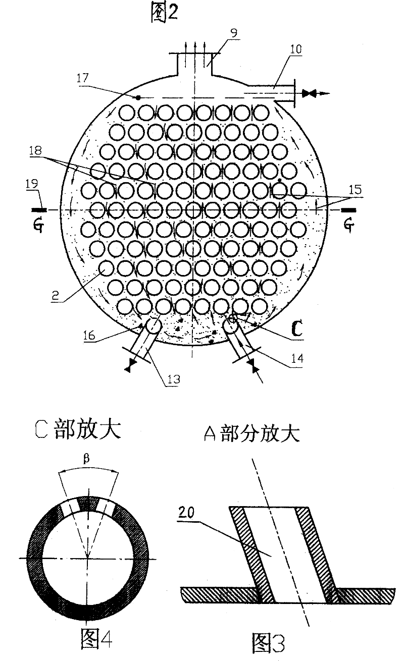
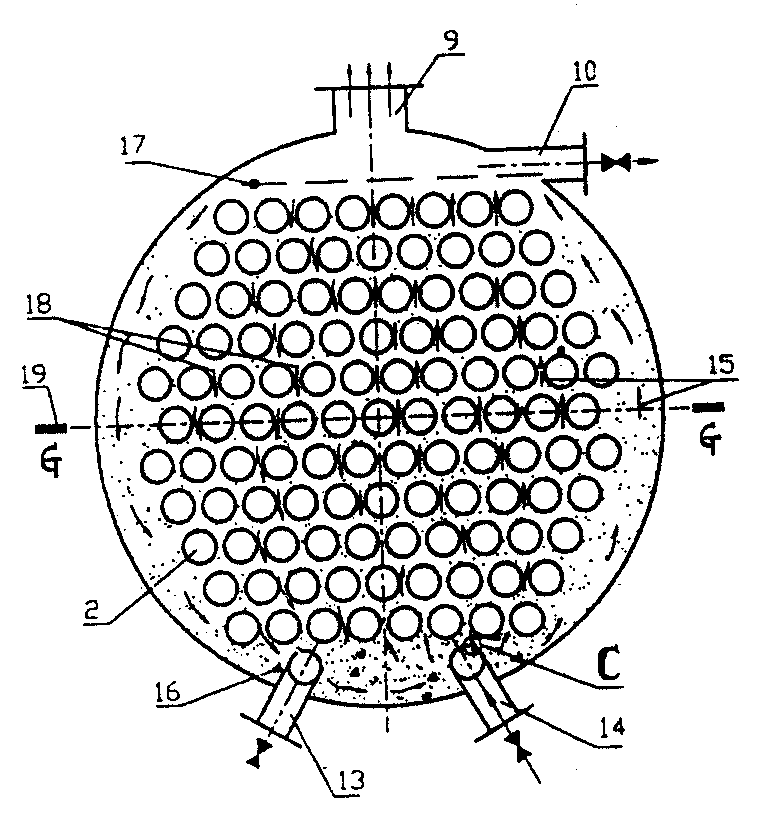
[0012] The following describes the specific implementation of the patented fluidized on-line shell-side shell-side heat exchanger in conjunction with accompanying drawings 1, 2, 3 and 4:

[0013] When cleaning the dirt outside the pipe during operation, open the right air supply valve 14, exhaust port 9 and overflow port 10 on the side of the shell, and close the liquid outlet 11 on the shell side. When the velocity of the cleaning gas at G-G19, the largest cross-section between the pipes, exceeds a certain value for the settling velocity of the particles there, the cleaning gas enters the bottom of the right half of the shell through the gas jet hole 3 or gas jet nozzle, and disperses into a large amount of steam. The upward buoyancy of the bubbles drives the shell-side liquid to move upward violently, and drives the fluidized particles 16 to flow upward 15 to the gas-liquid separation surface 17 controlled by the overflow port 10 , and the cleaning gas is separated and discha...


PUM


Abstract

Disclosed is an outside dirt three-phase circulation fluidized cleaning technology for a horizontal tubular heat exchanger. An air distribution pipe on which a lot of oblique gas orifices are arranged is mounted at the bottom of a casing. Cleaning gas is discharged from top exhaust ports. The cleaning technology is rapid, uniform and pollution free.

Description

technical field [0001] The patent of the present invention relates to a horizontal shell-and-tube heat exchanger with fluidized on-line cleaning of the shell side. This technology can be widely used in periodic on-line cleaning of dirt outside the tubes of various tube and tube heat exchangers. Background technique [0002] The horizontal shell-and-tube heat exchanger currently in use cannot be mechanically cleaned after the shell-side liquid fouls outside the tube during operation. It is almost a single chemical cleaning method, but due to structural reasons, the cleaning uniformity is poor, the effect is not good, and it is easy to cause local corrosion. Therefore, the dirt outside the pipe cannot be cleaned and removed in time, and the operating efficiency gradually decreases, deteriorates, and even partially blocked, leading to early failure and scrapping, which seriously affects the service life. Contents of the invention [0003] The patent of the present invention...

Claims


Application Information

Patent Timeline
Patent Type & Authority Patents(China)
IPC IPC(8): F28G1/12
Inventor 彭德其俞秀民俞天兰吴金香俞天翔林伟璐蒋少青张琳宁立伟
Owner 株洲工学院帅科机械清洗研究所
Why Eureka
Try Eureka