Support portion structure of pendant for vehicle

A technology for supporting parts and supporting parts, which is applied to the lower structure, upper structure, vehicle parts, etc., can solve the problems of increased cost, large number of parts, and many assembly man-hours, and achieves accurate connection operation and good workability.

Active Publication Date: 2007-12-19
MITSUBISHI MOTORS CORP
View PDF6 Cites 0 Cited by
  • Summary
  • Abstract
  • Description
  • Claims
  • Application Information

AI Technical Summary

Problems solved by technology

[0010] However, here, the second reinforcement plate 180 with a protruding flange is projected on the thick flat ring-shaped first reinforcement plate 170, and is arc welded to the upward wall portion 140, so the number of components is large. , the number of assembly man-hours is more, it is easy to lead to an increase in cost, and it is hoped to be improved

Method used


Image

  • Support portion structure of pendant for vehicle
  • Support portion structure of pendant for vehicle
  • Support portion structure of pendant for vehicle

Examples


Embodiment Construction

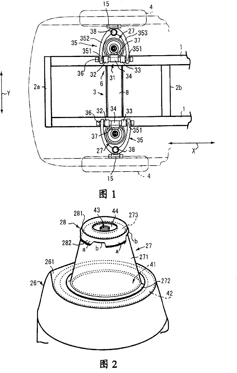
[0024] FIG. 1 shows a front portion of a vehicle body of a commercial vehicle to which a suspension support structure for a vehicle according to an embodiment of the present invention is applied.

[0025] The front part of the vehicle body includes a pair of left and right side beams 1 extending in the front-rear direction X, and a plurality of cross beams 2a, 2b, 3 arranged facing the vehicle width direction Y and connecting the side beams 1 on both sides.

[0026] Here, the beams are sequentially arranged rearward through the front beam 2a at the front end, the suspension beam 3 supporting the suspension components, the middle beam 2b, etc., and are respectively connected between the left and right side beams 1, thereby strengthening the strength of the front part of the vehicle body. .

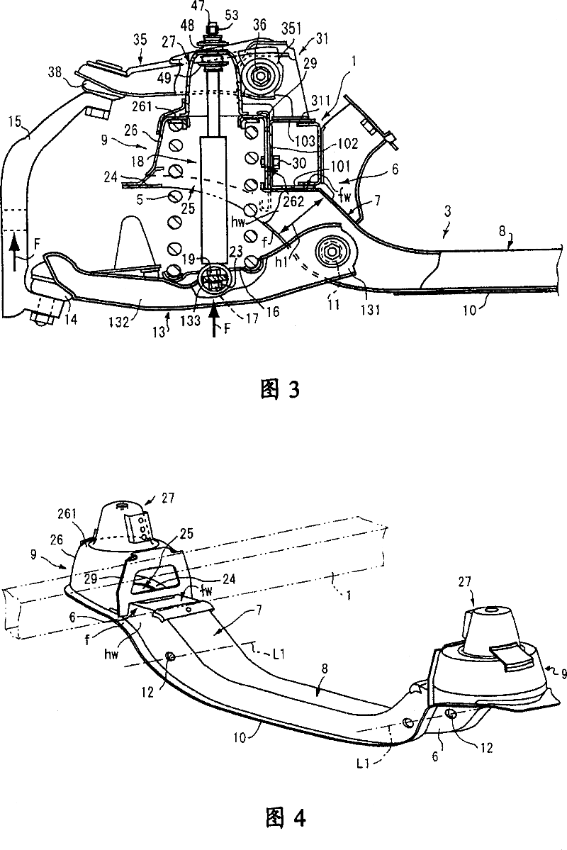
[0027] As shown in Figures 3 and 4, the suspension crossbeam 3 as a suspension support component includes: a pair of left and right connecting parts 6, which are connected and fixed on a pa...


PUM


Abstract

To provide support suspension structure for a vehicle capable of precisely fastening a shock absorber having excellent durability without causing increase of the number of parts or man-hour for assembling.

Description

technical field [0001] The present invention relates to a vehicle suspension support structure for mounting a shock absorber between a suspension support member on a vehicle body side and a vehicle suspension member supported by the suspension support member. Background technique [0002] Typically, vehicles are connected using multiple linkage members, springs, and shock absorbers. Among them, a plurality of link parts connect the joints between the body side and the wheel side and adjust the wheels; the spring continuously overcomes the road reaction force to support the body load; and the shock absorber absorbs and attenuates the body load generated by the road reaction force. shock. In such a suspension component, the lower end of the shock absorber is pin-connected to the lower cross arm of one of the link components, and the upper end thereof is swingably connected to the shock absorber support on one side of the vehicle body through a bolt rod and a vibration isolati...

Claims


Application Information

Patent Timeline
Patent Type & Authority Patents(China)
IPC IPC(8): B62D65/12B60G13/00B60G7/00B60G13/08B60G15/06B62D21/00B62D25/08F16F9/54
Inventor 樱井宽己
Owner MITSUBISHI MOTORS CORP
Why Eureka
Try Eureka