Stator core for linear motor

A linear motor and stator core technology, applied in the field of movers, can solve the problems of insufficient efficiency and complexity of the stator core, achieve high filling factor and reduce negative effects

Inactive Publication Date: 2007-12-26
HOGANAS AB
View PDF3 Cites 1 Cited by
  • Summary
  • Abstract
  • Description
  • Claims
  • Application Information

AI Technical Summary

Problems solved by technology

However, building this stator core onto the coils is more complex
[0010] Furthermore, the efficiency of the stator core according to US 6 060 810 is still not high enough in terms of the ratio of the generated force to the spatial volume of the motor

Method used


Image

  • Stator core for linear motor
  • Stator core for linear motor
  • Stator core for linear motor

Examples


Embodiment Construction

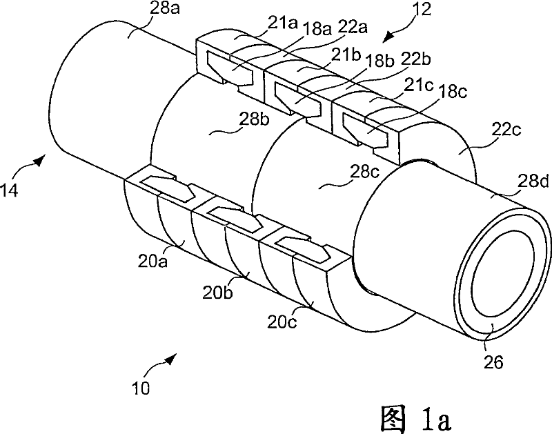
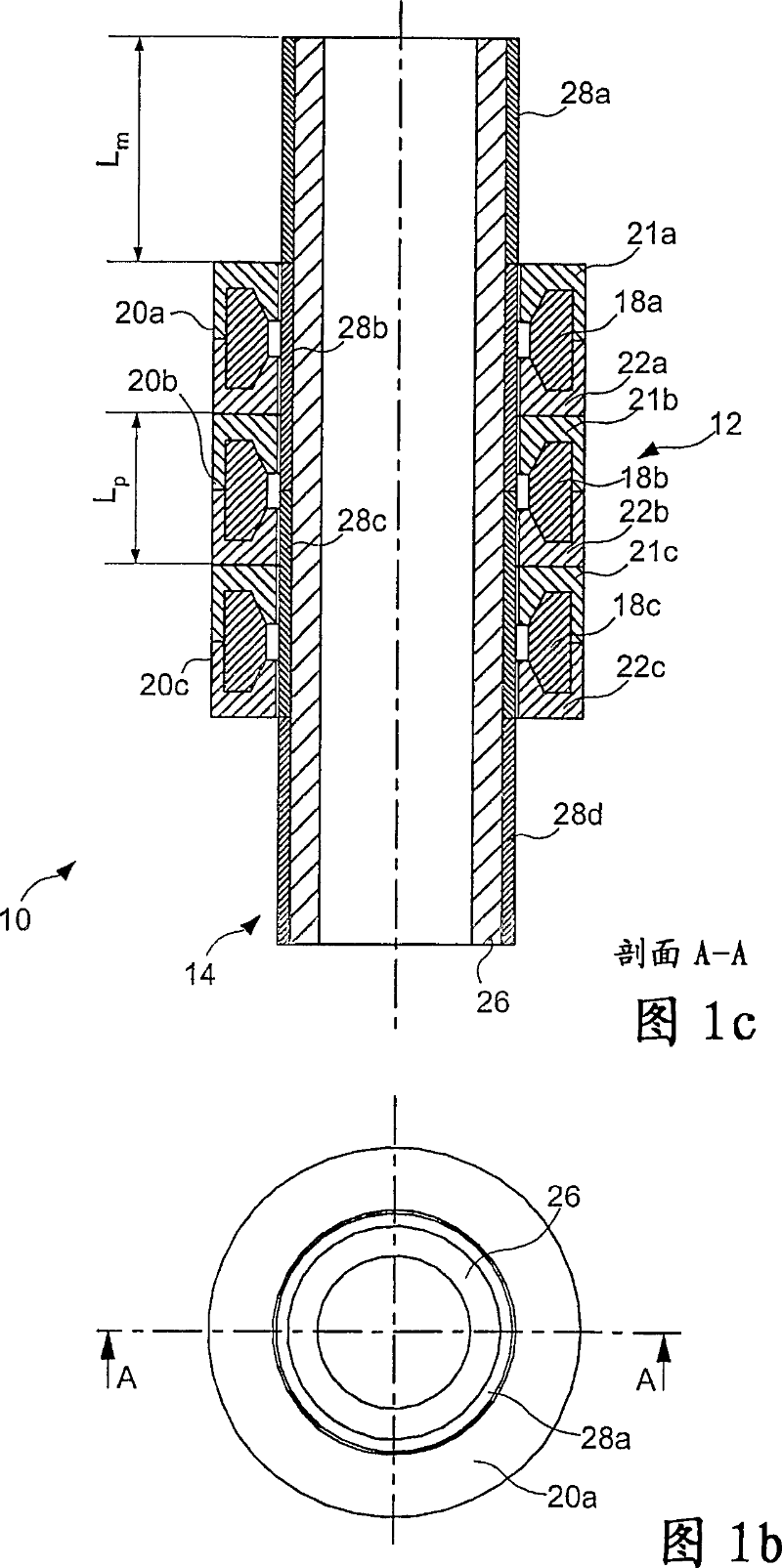
[0065] In Figs. 1a-c, a schematic diagram of a linear motor according to an embodiment is shown. The linear motor 10 includes a stator 12 and a mover 14 . Usually, the stator is stationary and drives the mover axially, however, it is also possible to make the mover stationary and let the stator drive itself axially. Thus, in the context of the present invention, axial is the direction of movement of either the mover or the stator, depending on which of the two will move relative to the other.

[0066] The stator includes at least one coil 18a-c and at least one stator core 20a-c. The stator coils can be a single winding, i.e. a wire wound into a coil and connected to a power supply unit not shown, or a distributed winding, i.e. each stator coil includes a different output port connected to the power supply unit and thus can transmit the Line(s) of current of different electrical characteristics. Those skilled in the art of electric motors know many different types of power ...


PUM


Abstract

A linear motor comprising a stator core and / or a mover. The stator core of said linear motor comprising an inner perimeter, an outer perimeter essentially encircling the inner perimeter, a first and a second tooth being arranged along one of the inner perimeter or the outer perimeter, a slot for receiving a stator coil, said slot being a cavity arranged within the stator core, wherein said stator core is divided into a first stator part and a second stator part, said first stator part including the first tooth, being arranged to partially define the slot, and being made of soft magnetic powder, and said second stator part including the second tooth, being arranged to partially define the slot, and being made of soft magnetic powder.

Description

technical field [0001] The invention relates to a linear motor, in particular to a linear motor, a stator core of the linear motor and a mover of the linear motor. Background technique [0002] Generally, the soft magnetic part also called core in electric motors and machines is made of soft magnetic material such as iron or core silicon steel insulating sheet. These insulating sheets of soft electrical material are also called laminates. The core is made of laminations to reduce the occurrence of eddy currents and thus increase the efficiency of motors and machines. [0003] In a linear motor with an annular stator core and a tubular mover, where the mover is the part of the linear motor that will be moved by interacting with the magnetic field of the stator, each metal plate is arranged in a radial and axial plane to Minimize the effects of eddy currents. [0004] In some linear motors, metal plates are stacked together in parallel to form a core section arranged such t...

Claims


Application Information

Patent Timeline
Patent Type & Authority Patents(China)
IPC IPC(8): H02K1/12H02K1/34H02K41/02H02K1/14H02K33/16
CPCH02K33/16H02K1/145
Inventor A·杰克P·G·迪金森L-O·彭纳德
Owner HOGANAS AB
Why Eureka
Try Eureka