
Display panel

A technology of display panel and substrate array, which is applied to static indicators, instruments, etc., can solve the problems of increasing the width of the surrounding area, unfavorable narrow frame requirements of the display panel, etc., and achieves the effect of satisfying demands, appearance and performance.

Pending Publication Date: 2020-02-07
HANNSTAR DISPLAY CORPORATION
View PDF9 Cites 1 Cited by
  • Summary
  • Abstract
  • Description
  • Claims
  • Application Information

AI Technical Summary

Problems solved by technology

On the other hand, for a display panel with an integrated gate driver, the gate driver and the pixel unit are disposed on the active array substrate and located in the peripheral area and the active area of ​​the display panel respectively, so the gate driver needs to be reserved in the peripheral area. configuration space, which will increase the width of the peripheral area, which is not conducive to the narrow bezel requirements of the display panel

Method used


Image

  • Display panel
  • Display panel
  • Display panel

Examples


Embodiment Construction

[0027] Embodiments of the invention are discussed in detail below. It should be appreciated, however, that the embodiments provide many applicable concepts that can be implemented in a wide variety of specific contexts. The discussed and disclosed embodiments are for illustration only, and are not intended to limit the scope of the present invention.

[0028] It can be understood that although the terms "first", "second", "third"... etc. may be used herein to describe various elements, parts, regions and / or sections, these terms should not limit these element, part, region and / or section. These terms are only used to distinguish one element, component, region and / or section from another element, component, region and / or section.

[0029] The terminology used herein is for describing particular embodiments only, not for limiting the claims. Unless otherwise limited, the terms "a" or "the" in the singular may also be used to refer to the plural. In addition, the use of spati...


PUM


Abstract

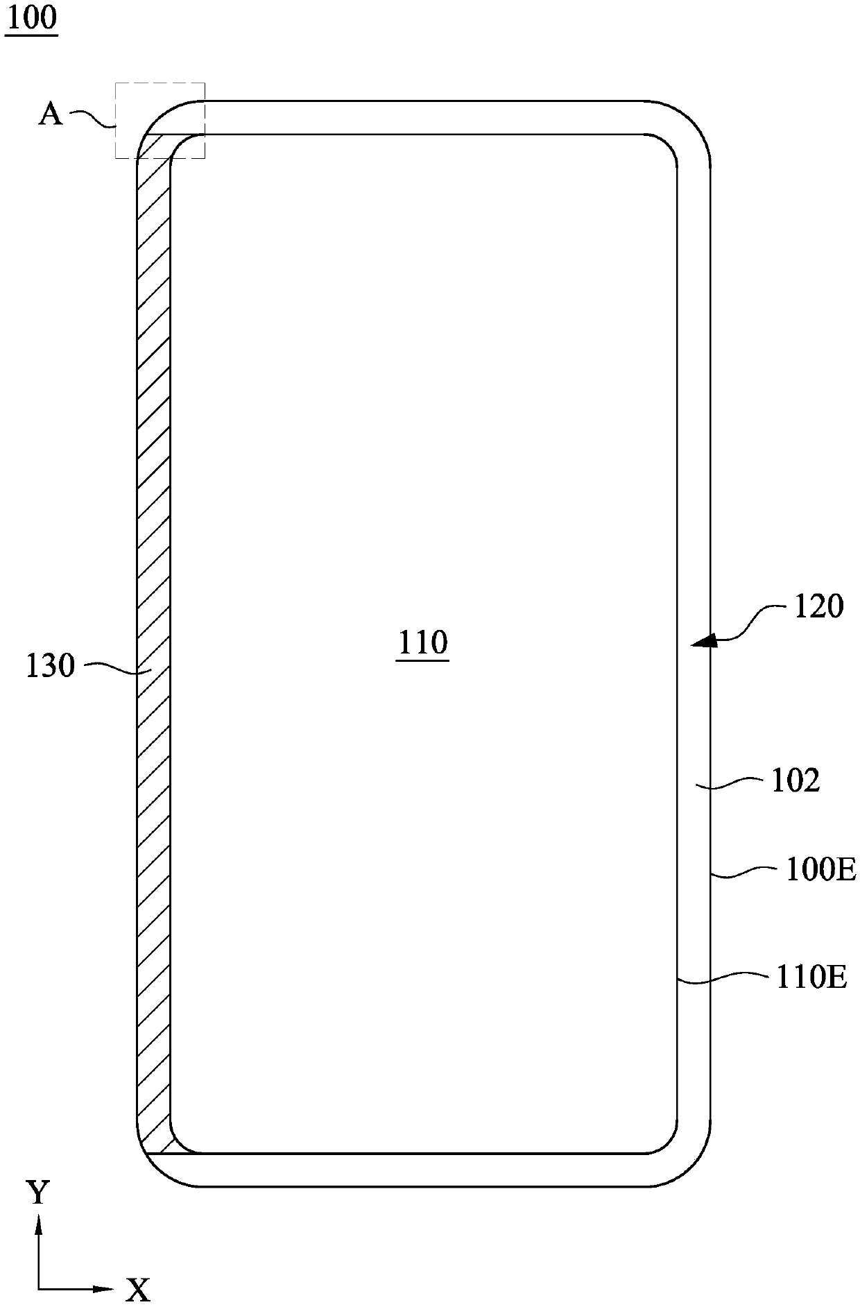
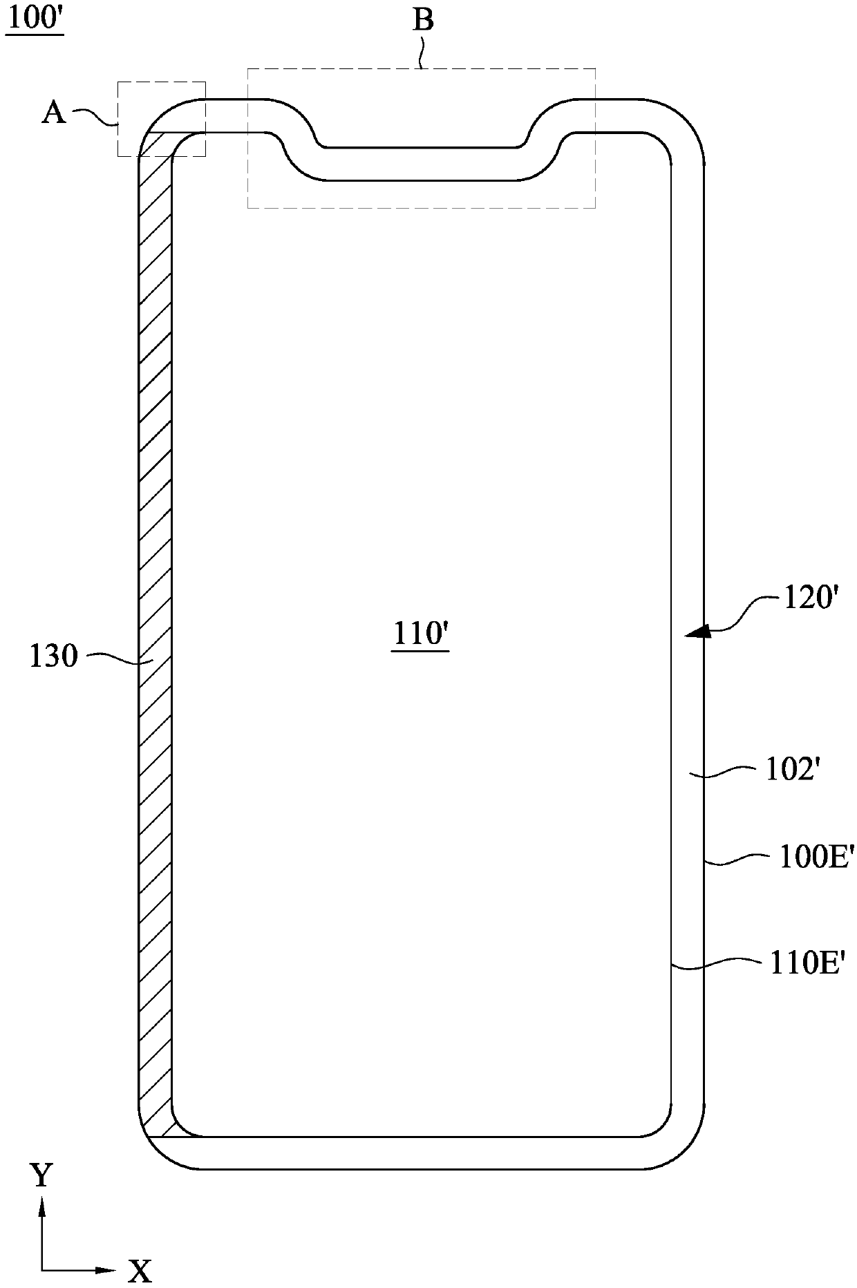
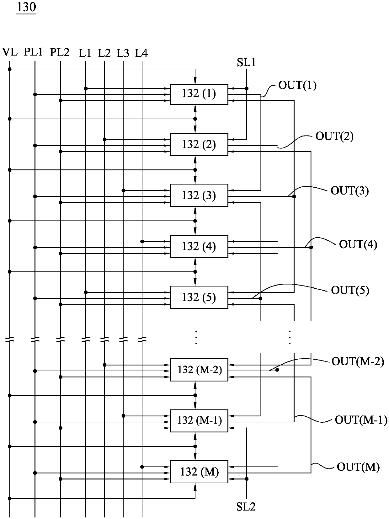
The invention discloses a display panel, which is provided with a special-shaped active region and a peripheral region, and comprises a plurality of pixel units, a plurality of gate lines and a substrate array row driving circuit, the plurality of pixel units are located in the special-shaped active area. The plurality of gate lines are located in the special-shaped active region and are coupled to the plurality of pixel units respectively. The substrate array row driving circuit is located in the peripheral area and comprises a plurality of shift registers and a plurality of clock signal lines. The plurality of shift registers are located in the peripheral region and are coupled to the plurality of gate lines, respectively. The plurality of clock signal traces are located in the peripheral region and are coupled to the plurality of shift registers, respectively. At least one clock signal line in the plurality of clock signal lines comprises a first part, a second part and a third part, the included angle between the first part and the second part is an obtuse angle, and the included angle between the second part and the third part is an obtuse angle. The display panel containing the substrate array row driving circuit and the special-shaped active area can be manufactured, and the requirements of consumers for appearance and efficiency can be met.

Description

technical field [0001] The invention relates to a display panel, and in particular to a display panel with a special-shaped active area. Background technique [0002] With the evolution of display panel manufacturing technology, today's high-resolution display panels can be applied to wearable and handheld electronic products, such as smart watches, health bracelets, etc. On the other hand, consumers' demand for aesthetics of electronic products is increasing day by day, and display panels with special exterior designs are therefore applied to electronic products. Display panels on these electronic products usually have a non-rectangular shape, such as a circle or other irregular shapes. On the other hand, for a display panel with an integrated gate driver, the gate driver and the pixel unit are disposed on the active array substrate and located in the peripheral area and the active area of ​​the display panel respectively, so the gate driver needs to be reserved in the per...

Claims


Application Information

Patent Timeline
IPC IPC(8): G09G3/20G09G3/36
CPCG09G3/20G09G3/3677
Inventor 游家华林松君胡宪堂刘轩辰詹建廷
Owner HANNSTAR DISPLAY CORPORATION
Learn More