Cooler for several heating elements

A technology for heating elements and cooling devices, which is applied to electrical components, cooling/ventilation/heating transformation, electrical solid-state devices, etc., and can solve problems such as burnout, difficult positioning of cooling blocks and heating elements, and poor heat dissipation capability of microprocessors.

Inactive Publication Date: 2008-01-23
FU ZHUN PRECISION IND SHENZHEN +1
View PDF12 Cites 0 Cited by
  • Summary
  • Abstract
  • Description
  • Claims
  • Application Information

AI Technical Summary

Problems solved by technology

[0008] (1) The body of the cooling device is too heavy, and long-term use will cause damage to the circuit board
[0009] At present, the existing heat dissipation technology is used on high-power dual microprocessors. The most common method is to use an axial fan to fix the radiator at the top of the heat dissipation fins. With the increasing heat generation of microprocessors year by year, there are solutions It is nothing more than increasing the size of the cooling fins and increasing the size and speed of the fan. In a vertical computer case, the circuit board is usually installed vertically on the ground. It is easy to cause distortion of the circuit board, and when the heat sink is too heavy, it is easy to fall out of its original position under the influence of gravity or vibration
[0010] (2) The uneven distribution of air flow affects the cooling effect
[0011] Another existing technology is to install a heat dissipation fin on the dual microprocessors respectively, and guide the external airflow to the two heat dissipation fins through the fan group installed inside the server, and then discharge the preheated airflow to the outside In order to achieve the purpose of heat dissipation, however, the positions of the two microprocessors are different, which in turn affects the airflow rate of the fan to the fins, resulting in different heat dissipation levels of the two microprocessors, resulting in a lower airflow rate at the end far away from the fan. It is difficult for the microprocessor to be fully cooled by the cold air flow, resulting in poor heat dissipation of the microprocessor and overheating and burning
[0012] (3) The installation steps of the evaporator device are cumbersome
[0013] There are too many accessories and parts in the evaporator, resulting in cumbersome processing steps, which also increases the manufacturing cost and the defect rate, and the user is not only time-consuming and laborious in the installation, but also easily increases the negligence in the installation process
[0014] (4) The serial cooling system cannot exert the best heat transfer function
[0015] The conventional heat dissipation system uses a serial cooling method, as shown in Figure 1, which uses a fluid to flow through the first microprocessor for cooling, and the fluid after heat removal has been preheated to a high-temperature fluid, so that sufficient cooling cannot be ensured. Cooling capacity to remove heat from the second microprocessor, resulting in an imbalance in the cooling of the dual microprocessors
[0016] (5) The positioning between the cooling block and the heating element in the evaporator device is not easy
[0019] Since the precision electronic parts on the circuit board are quite sensitive to moisture and moisture, the amount of moisture accumulated by the two cooling blocks in the double evaporator and the distribution range of the moisture on the circuit board are more than double that of the single block. There is no moisture isolation structure design between the cooling block and the circuit board, which will cause excessive moisture and moisture to seep into the circuit board. If the impact is mild, it will cause the aging of the circuit board circuit and shorten the service life of the circuit board. It will be burned due to the current short circuit of the parts on the circuit board

Method used


Image

  • Cooler for several heating elements
  • Cooler for several heating elements
  • Cooler for several heating elements

Examples


Embodiment Construction

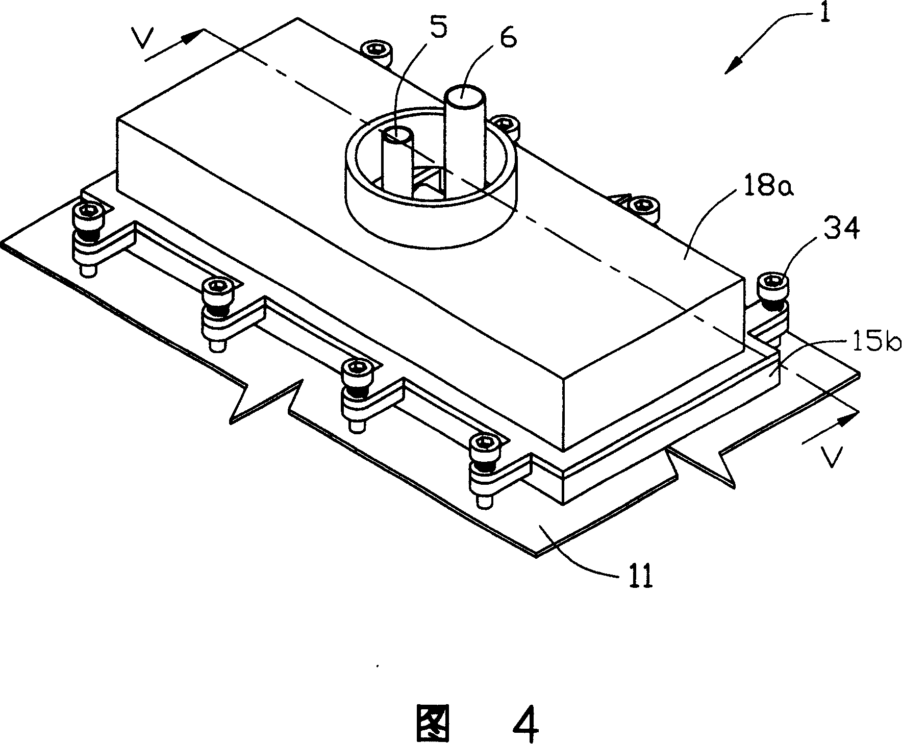
[0036] FIG. 3 is a schematic diagram of the principle of the compression refrigeration cycle system used in the cooling device for several heating elements (for simplicity of description, hereinafter referred to as the cooling device) in this embodiment. The cooling device of this embodiment is used to remove the heat generated by the microprocessor 10 disposed on a circuit board 11 . It can be understood that the cooling device of this embodiment can also be used to cool other electronic components and non-electronic components with several heat sources. In order to simplify the description, two microprocessors are taken as examples for illustration below.

[0037] The cooling device includes an evaporator 1 , a compressor 2 , a condenser 3 and a pipeline for transporting refrigerant, and the pipeline for refrigerant includes a capillary liquid inlet pipe 5 and an air outlet pipe 6 .

[0038] The evaporator 1 includes two cooling blocks 15 , it can be understood that the num...


PUM


Abstract

The invention provides a cooling device used for plural heating elements. It includes compressor, condenser, evaporator, and cool medium cycling loop. The evaporator includes at least two cooling block adhering to the heating element. A splitter box connects cooling block flow channel and transferring cool medium pipeline. The evaporator also includes a casing and bottom board to sealing the cooling block in it to avoid the humidity filtering into the circuit board. Pressing components are set between casing and cooling block to make the cooling block contact with heating element tightly to improve heat emission effect.

Description

【Technical field】 [0001] The invention relates to a circulating cooling device. 【Background technique】 [0002] With the growth of the global electronic industry technology year by year, the technological development of the central microprocessor (CPU) of the computer is also constantly innovating, which makes the microprocessor develop towards the trend of fast computing clock pulse and enhanced performance, which in turn leads to the consumption of the microprocessor The power is increased and the heat generation is greatly increased. Recently, the pioneers in the development of the world's advanced electronic technology have encountered unprecedented bottlenecks due to the inability to break through the heat dissipation caused by the huge power consumption of the chips in the microprocessor. They have given up research and development when they cannot maintain the stable operation of the system. Faster microprocessors. Dividing the current single CPU into dual CPUs to s...

Claims


Application Information

Patent Timeline
Patent Type & Authority Patents(China)
IPC IPC(8): G06F1/20H05K7/20H01L23/473
Inventor 李志鹏刘泰健
Owner FU ZHUN PRECISION IND SHENZHEN
Why Eureka
Try Eureka