Steel (iron) water slag-removing method
A technology of molten iron and molten steel, applied in mechanical cleaning, manufacturing tools, metal processing equipment, etc., can solve the problems of increasing production costs, reducing production efficiency, time-consuming and labor-intensive, etc., and achieves the effects of saving paint, easy cleaning, and flexible layout
- Summary
- Abstract
- Description
- Claims
- Application Information
AI Technical Summary
Problems solved by technology
Method used
Image

Examples
Embodiment 1
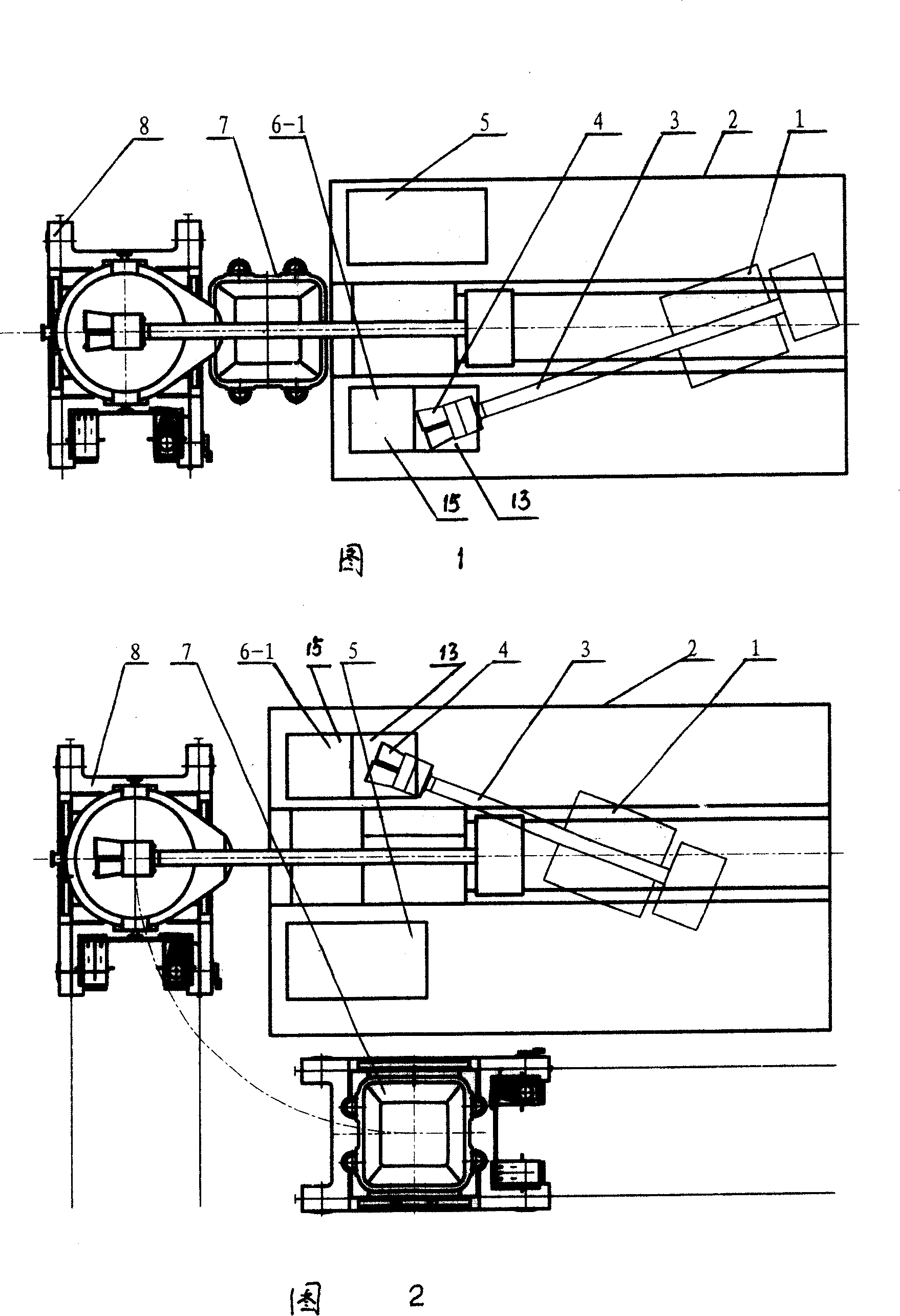
[0018] As shown in Figure 1, firstly, make the slag removing machine 1 be at the slag removing position, that is, the slag rake 4 is located at the molten steel or molten iron bag position 8, and implement the slag rake rotation to remove slag; Back to the slag unloading station, that is, the slag rake 4 is located at the slag hopper position 7, and the slag is unloaded; the above two steps are carried out alternately.
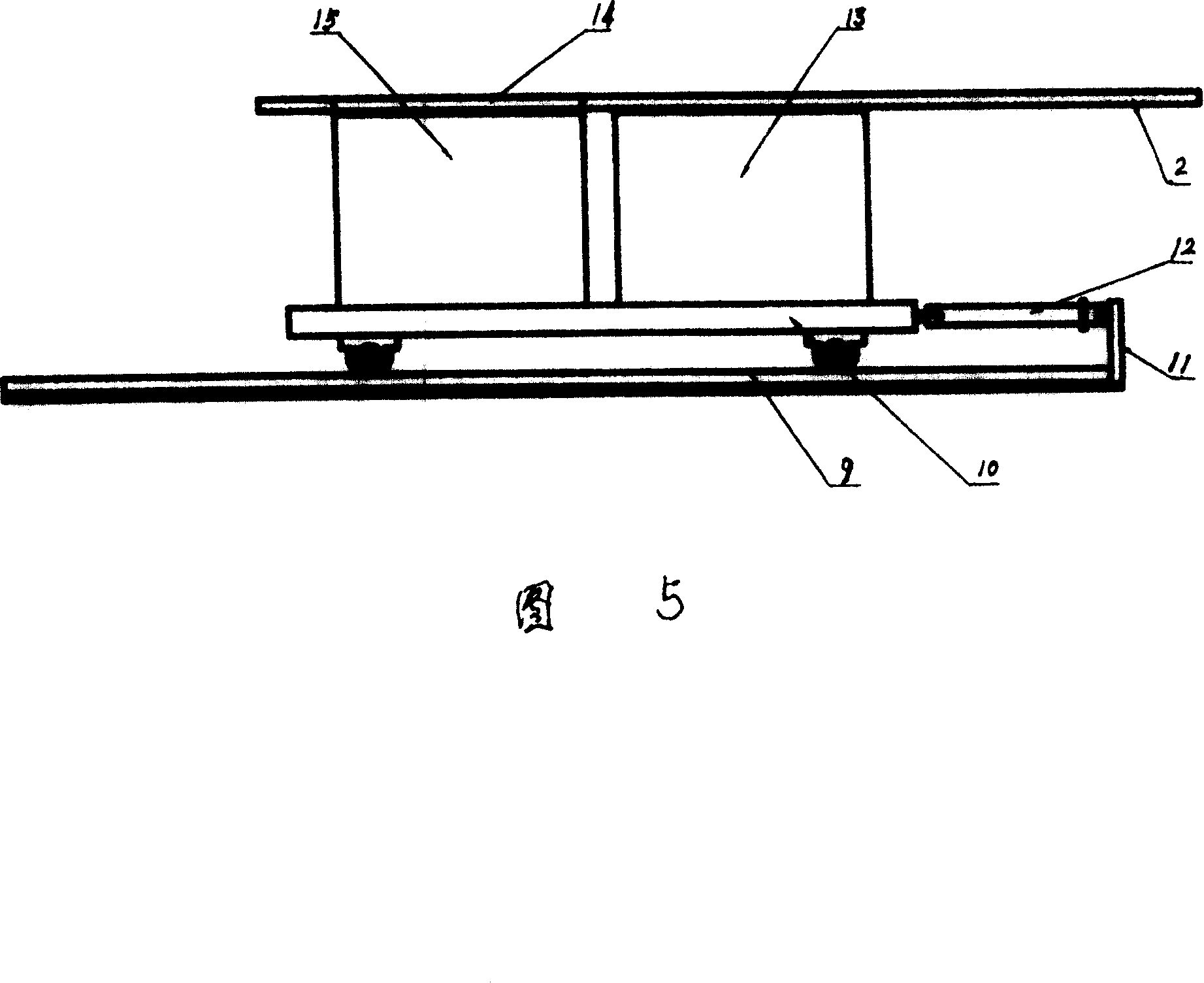
[0019] After a ladle of molten steel or molten iron is slag removed, the slag rake 4 is rotated with the cantilever 3 to the water-cooling dip-coating station 6-1, and the water-cooling or dip-coating or water-cooling+dip-coating operation of the slag rake 4 is implemented. Wherein, the water cooling is carried out in the cooling pool 15, and the dip coating is carried out in the coating pool 13.
Embodiment 2
[0021] As shown in Figure 2, firstly, make the slag removing machine 1 be at the slag removing position, that is, the slag rake 4 is located at the molten steel or molten iron bag position 8, and implement the slag rake rotation to remove slag; Rotate to the slag unloading station, that is, the slag rake 4 is located at the slag hopper position 7, and the slag is unloaded; the above two steps are carried out alternately.
[0022] After a ladle of molten steel or molten iron is slag removed, the slag rake 4 is rotated with the cantilever 3 to the water-cooling dip-coating station 6-1, and the water-cooling or dip-coating or water-cooling+dip-coating operation of the slag rake 4 is implemented. Wherein, the water cooling is carried out in the cooling pool 15, and the dip coating is carried out in the coating pool 13.
Embodiment 3
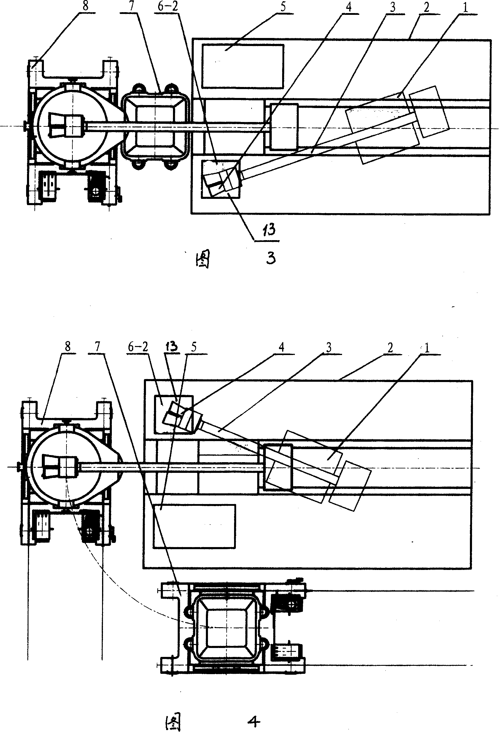
[0024] As shown in Figure 3, firstly, make the slag removing machine 1 in the slag removing position, that is, the slag rake 4 is located at the molten steel or molten iron ladle position 8, and implement the slag rake rotation to remove slag; Back to the slag unloading station, that is, the slag rake 4 is located at the slag hopper position 7, and the slag is unloaded; the above two steps are carried out alternately.
[0025] After a ladle of molten steel or molten iron is slag removed, the slag rake 4 is rotated with the cantilever 3 to the dip coating station 6-2, and the slag rake 4 is dip-coated in the coating pool 13.
PUM
 Abstract
Description
Claims
Application Information
 - R&D
- Intellectual Property
- Life Sciences
- Materials
- Tech Scout
- Unparalleled Data Quality
- Higher Quality Content
- 60% Fewer Hallucinations
Browse by: Latest US Patents, China's latest patents, Technical Efficacy Thesaurus, Application Domain, Technology Topic, Popular Technical Reports.
© 2025 PatSnap. All rights reserved.Legal|Privacy policy|Modern Slavery Act Transparency Statement|Sitemap|About US| Contact US: help@patsnap.com