Double cross arm suspension guiding mechanism of non-steering wheel

A guide mechanism, double wishbone technology, applied in suspension, elastic suspension, transportation and packaging, etc., can solve problems such as difficulty and time-consuming, and achieve the effect of reducing manufacturing cost, simplifying mechanism design and manufacturing, and reducing types.

Inactive Publication Date: 2008-01-30
同济大学新能源汽车工程中心 +1
View PDF6 Cites 0 Cited by
  • Summary
  • Abstract
  • Description
  • Claims
  • Application Information

AI Technical Summary

Problems solved by technology

Theoretically, through trial and error or analysis of the motion of the guiding mechanism, a mechanism that meets the practical requirements can always be found, but such a design is blind, time-consuming and difficult to obtain good results

Method used


Image

  • Double cross arm suspension guiding mechanism of non-steering wheel

Examples


Embodiment Construction

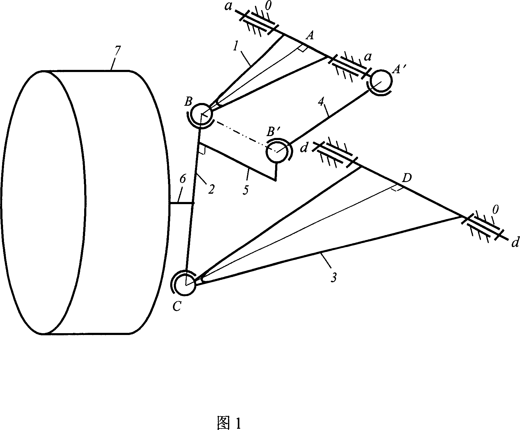
[0007] The present invention will be further described below in conjunction with accompanying drawing 1.

[0008] The present invention comprises vehicle frame 0, upper cross arm 1, steering knuckle 2, lower cross arm 3, double spherical hinge pull rod 4, joint arm 5, axle 6 and wheel 7, wherein one end of upper cross arm 1 is fixed hinge pin shaft aa is hinged with the frame 0, the other end is hinged with a ball joint to the steering knuckle 2 at point B, draw a vertical line from point B to the hinge pin axis aa, intersect the vertical foot at point A, and AB is the length of the upper cross arm 1; The upper end of the steering knuckle 2 and the upper cross arm 1 are hinged at point B with a ball hinge, and the lower end and the lower cross arm 3 are hinged at point C with a ball hinge. BC is the rod length of the steering knuckle 2; one end of the lower cross arm 3 is fixed with a The hinge pin axis d-d is hinged with the frame 0, and the other end is hinged with a ball jo...


PUM


Abstract

Said invention discloses non-steering wheel double cross arm guide mechanism for eliminating additional steering interference generated by vertical bouncing of wheel, which consists of frame, upper cross arm, kunckle and wheel etc wherein one end of upper cross arm in hinged with frame by fixing pin, another end is hinged with knuckle by ball joint.

Description

technical field [0001] This invention relates to a vehicle mechanism and, more particularly, to a double wishbone suspension guide mechanism utilizing non-steering wheels that does not produce additional steering. Background technique [0002] With the improvement of people's living standards, cars are used more and more widely, and people's requirements for cars are getting higher and higher, and the development of cars is developing in the direction of comfort and light weight. The driving form of traditional vehicles is driven by internal combustion engines. In recent years, electric vehicles and hybrid vehicles have developed rapidly. The existing driving schemes of vehicle power include series, parallel and hybrid. There are pros and cons to layout, price, and prime mover selection. Four-wheel drive electric vehicles can directly drive each wheel with four electric drive wheel modules with the same structure, but in a two-wheel steering four-wheel drive electric vehicl...

Claims


Application Information

Patent Timeline
Patent Type & Authority Patents(China)
IPC IPC(8): B60G3/18
Inventor 万钢陈辛波卓桂荣余卓平
Owner 同济大学新能源汽车工程中心
Why Eureka
Try Eureka