Method and device for measuring displacement/distance based on supersonic wave or sonic continuous sound-field phase-demodulating principle

A technology of distance measurement and ultrasonic, which is applied in the field of displacement/distance measurement and its device based on the principle of ultrasonic or acoustic continuous sound field phase discrimination.

Inactive Publication Date: 2008-01-30
深圳市有为信息技术发展有限公司
View PDF2 Cites 2 Cited by
  • Summary
  • Abstract
  • Description
  • Claims
  • Application Information

AI Technical Summary

Problems solved by technology

Similarly, when the single pulse emission stops, the mechanical inertia leaves the emission sensor with an aftershock that decays with an exponential curve (see Figure 3), which is also unfavorable for subsequent signal processing
Therefore, this method of signal transmission and reception cannot obtain high repeatability. Even if the resolution of the device is improved (some papers claim that it can be as high as ns-level high resolution), due to poor signal-to-noise ratio and poor repeatability, Such an excessively high resolution is essentially meaningless
[0010] (C) The traditional single-pulse gap working method is the flying point method (TOF), which can only perform the second cycle measurement after the receiving sensor receives the measurement echo of the previous single pulse, so the measurement period (T) varies with the range It is impossible to get a higher data output rate, so the dynamic tracking performance is poor, which seriously limits the application of this method in dynamic detection
For example, for an ultrasonic length measurement or displacement measurement device with a range of 10m, its maximum output data rate will not exceed 17Hz. For a system that combines transmission and reception with a single head, the conversion time of transmission and reception and D / A conversion are required. Not only There will be measurement blind spots, and the output data rate will be lower

Method used


Image

  • Method and device for measuring displacement/distance based on supersonic wave or sonic continuous sound-field phase-demodulating principle
  • Method and device for measuring displacement/distance based on supersonic wave or sonic continuous sound-field phase-demodulating principle
  • Method and device for measuring displacement/distance based on supersonic wave or sonic continuous sound-field phase-demodulating principle

Examples


Embodiment Construction

[0041] Below in conjunction with accompanying drawing, specific implementation is illustrated, and the present invention is further theoretically deduced and described in detail;

[0042] The layout, structure and working steps of the principle, method and measuring device of the displacement or distance phase detection based on the ultrasonic continuous sound field of the present invention are as follows:

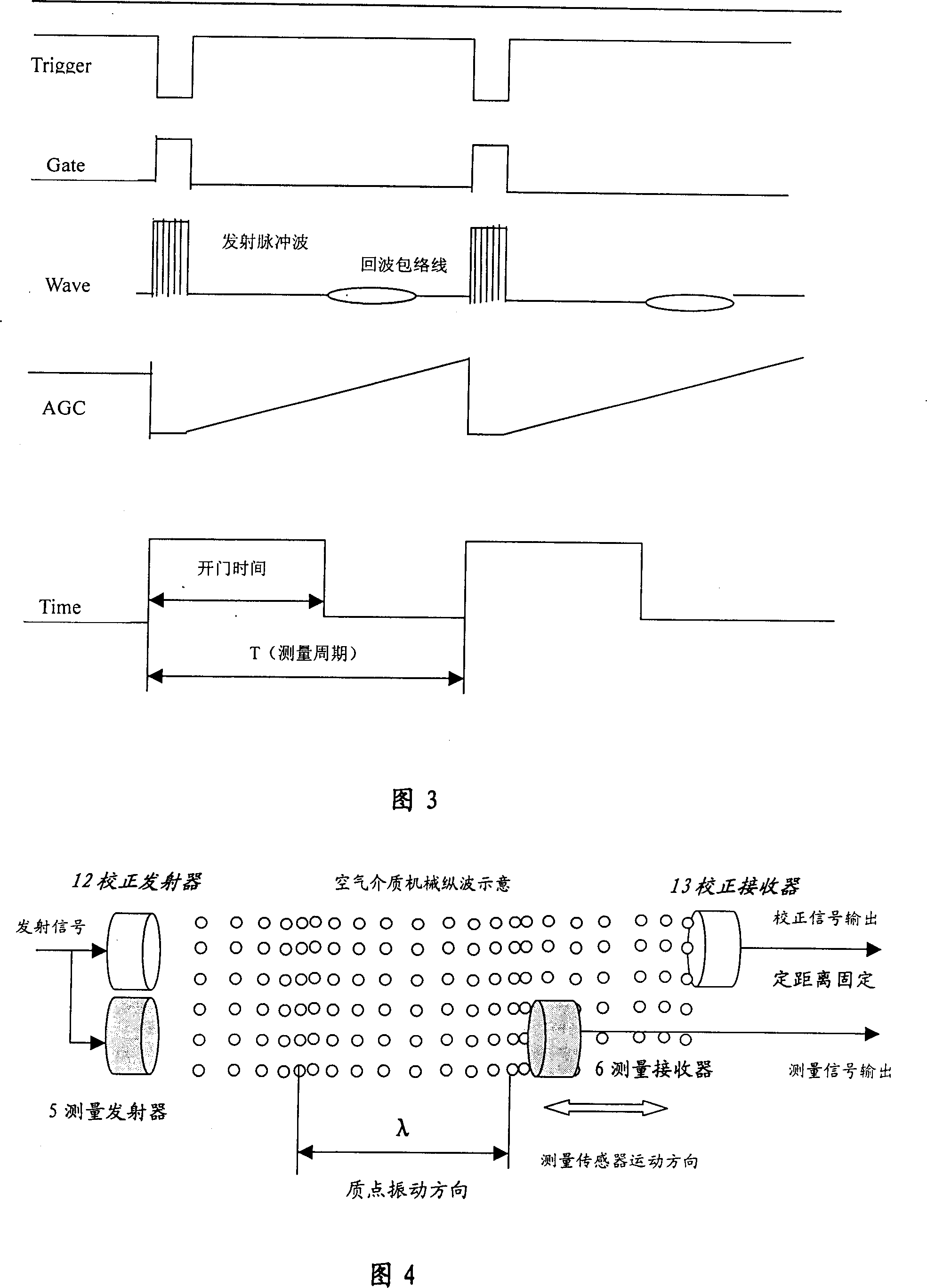
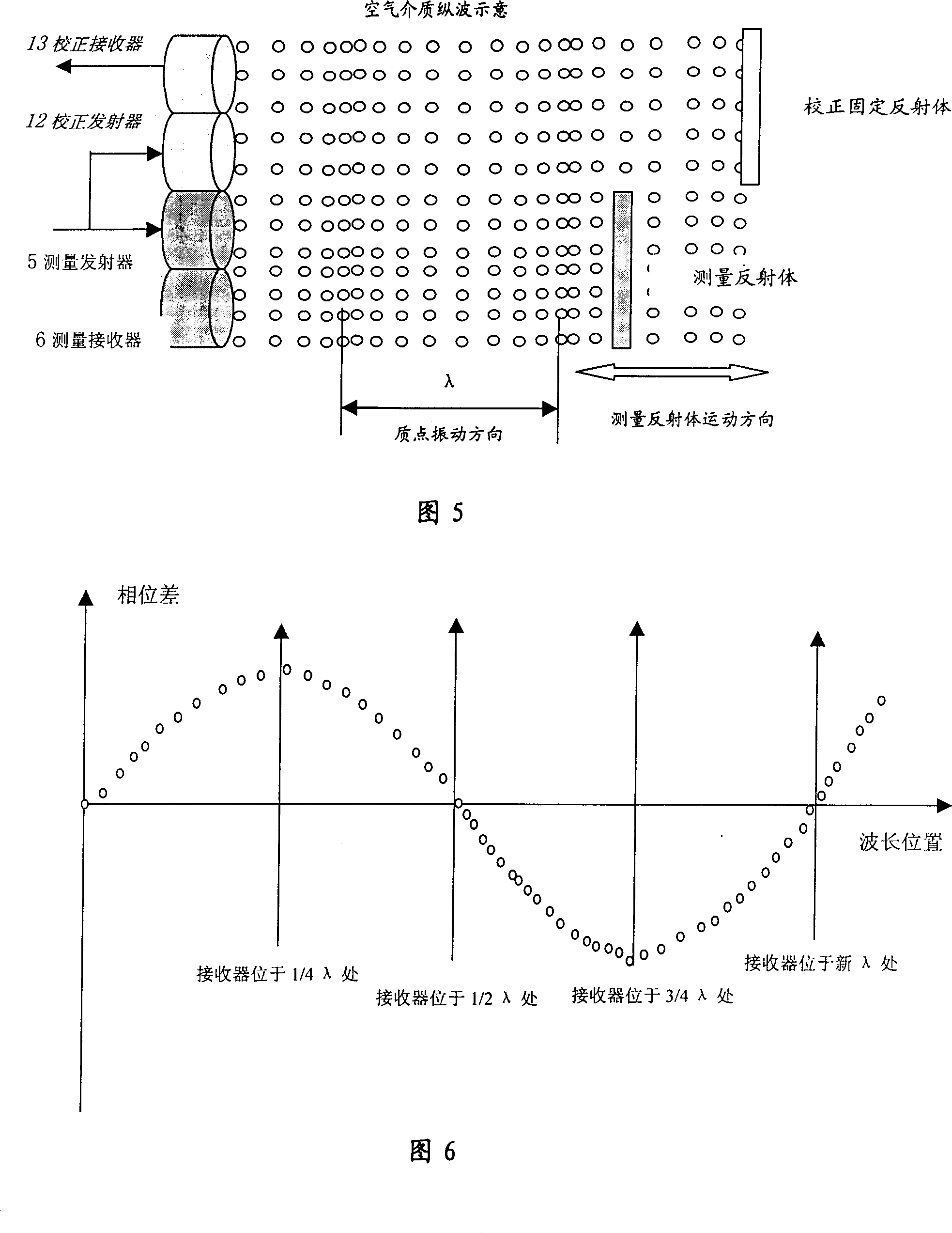
[0043] 1) Opposite-beam arrangement: Referring to Fig. 4, an ultrasonic transmitter 5 is arranged in the main measurement channel, and a receiver 6 is arranged at the other end, one of which is fixed, and the other can move relative to the measurement object; for self-adaptive, comprehensive To correct the errors caused by environmental factors, a specific error comprehensive correction correction channel can be arranged, wherein the transmitter 12 can be simultaneously stimulated by the signal of the transmitter 5, the receiver 13 and the transmitter 12 are relatively fixe...


PUM


Abstract

A method for measuring displacement / distance based on principle of continuous sound field phase discrimination for ultrasonic wave or sound wave includes equally dividing sound pressure wavelength received by receiver to be at least 28-210 fine broken number as per phase in period of operating frequency for ultrasonic or sonar transducer, obtaining increment counting pulse of coarse bit code through logic operation based on phase code for outputting data rate up to 40 KH2.

Description

Technical field [0001] The present invention relates to a method and device for measuring the dynamic displacement or distance of a measured object with ultrasonic waves or sound waves in a gas or liquid medium. A method of sound wave phase to determine its dynamic displacement or distance code (digital quantity) and its corresponding measuring device. technical background [0002] Ultrasonic or sound wave (hereinafter referred to as ultrasonic) has a long history of measuring length, distance and displacement, and it is also a promising, mature, non-destructive and non-contact measurement method. Since the beginning of the new century, the rapid development of high-tech, industry, national defense equipment and civil fields calls for new breakthroughs in the technical indicators of ultrasonic length measurement, distance measurement and displacement measurement on the existing basis. If the main technical indicators such as output data rate, resolution, repeatability, and ...

Claims


Application Information

Patent Timeline
Patent Type & Authority Patents(China)
IPC IPC(8): G01S15/08G01S15/32
Inventor 汪柏年
Owner 深圳市有为信息技术发展有限公司
Why Eureka
Try Eureka