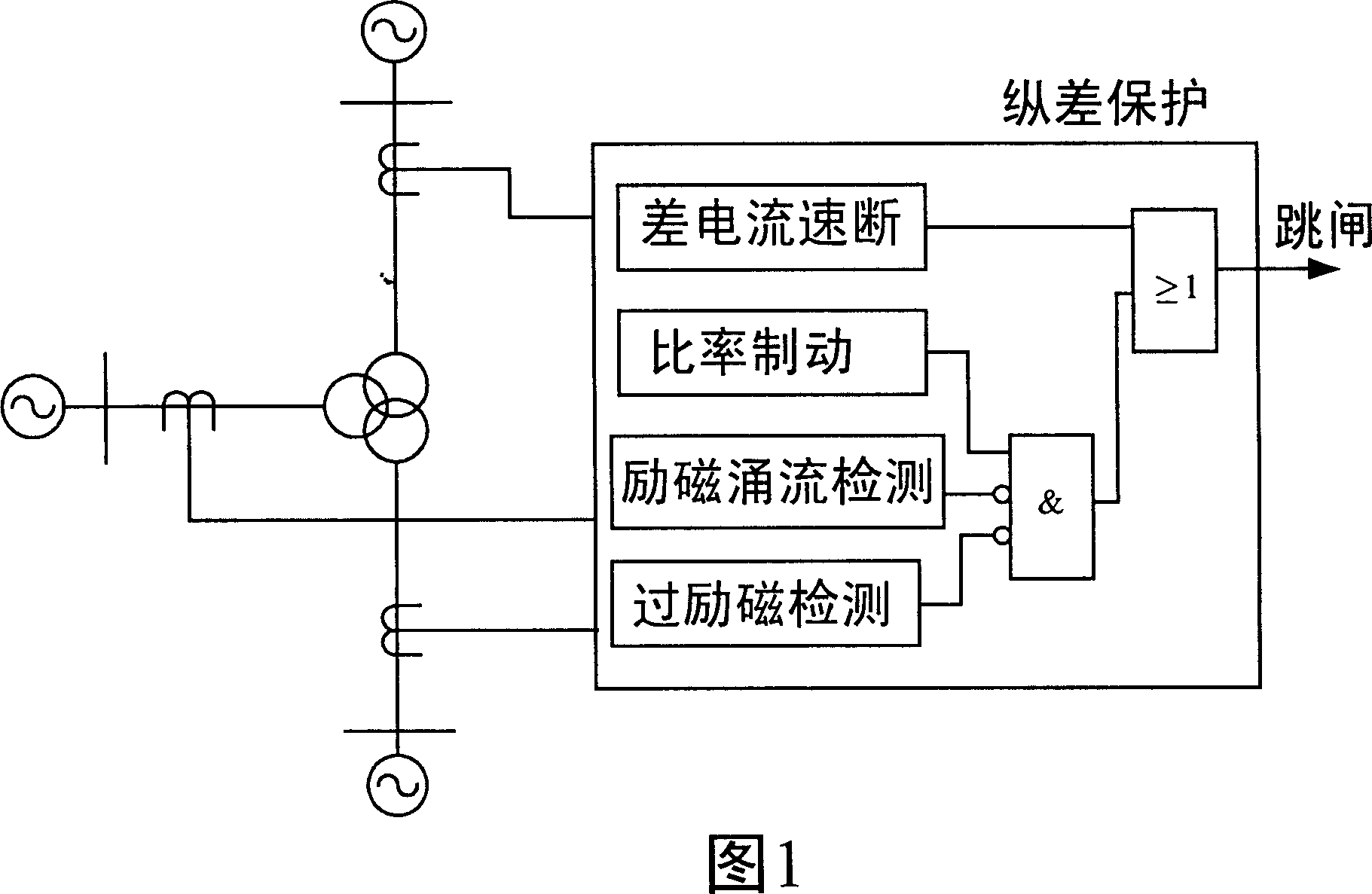
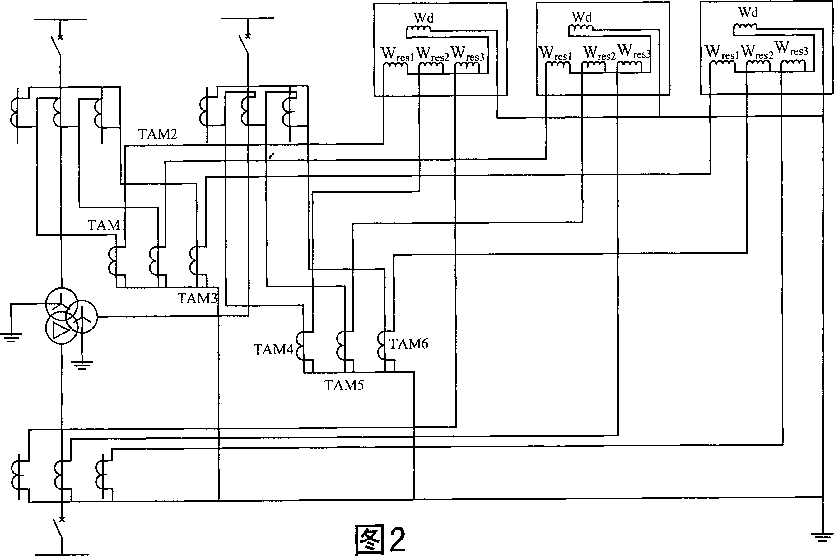
Transformer longitudinal error protective method with multiple side zero sequence ratio brake
A technology of zero-sequence current and ratio braking, applied in emergency protection circuit devices, electrical components, etc., can solve the problem that zero-sequence current cannot be completely eliminated, and achieve the effect of avoiding inconsistencies in errors
- Summary
- Abstract
- Description
- Claims
- Application Information
AI Technical Summary
Problems solved by technology
Method used
Image
Examples
Embodiment 1
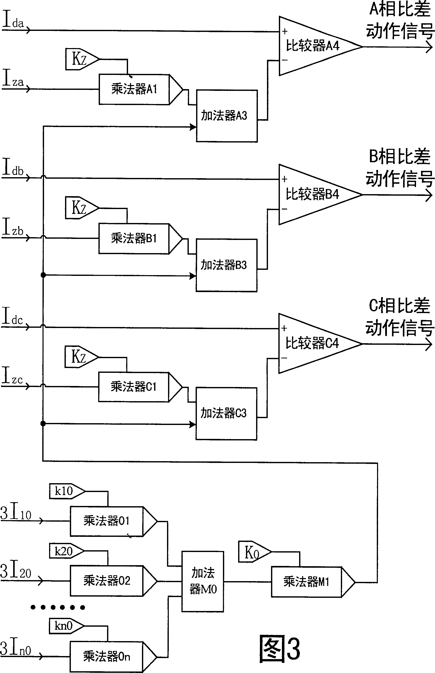
[0016] A transformer longitudinal differential protection method with multi-side zero-sequence current ratio braking, which can be realized through the circuit block diagram of a transformer longitudinal differential protection ratio braking component with multi-side zero-sequence current ratio braking in Figure 3 . This element consists of a multiplier A 1 , B 1 、C 1 , M 1 , 01, 02, 03, Adder A 3 , B 3 、C 3 , M 0 , and Comparator A 4 , B 4 、C 4 constitute. where multiplier A 1 , B 1 、C 1 One of the input terminals of the transformer differential protection respectively inputs the filtered three-phase braking current signal I representing the through current za , I zb , I zc , and its other input end enters the ratio brake coefficient K Z =0.4; one input terminal of the multiplier 01, 02, 03 respectively inputs the filtered zero-sequence current signal 3I of each neutral point grounding side (or branch) of the transformer 10 , 3I 20 , 3I 30 , and the other ...
Embodiment 2
[0018]A transformer longitudinal differential protection method with multi-side zero-sequence current ratio braking, which can be obtained through the circuit block diagram of another transformer longitudinal differential protection ratio braking component with multi-side zero-sequence current ratio braking in Figure 4 accomplish. This element consists of the subtractor A 11 , B 12 、C 13 , Multiplier A 21 , B 22 、C 23 , 011, 021, 031, M 4 , Adder A 31 , B 32 、C 33 、A 41 , B 42 、C 43 , M 3 and comparator A 51 , B 52 、C 53 constitute. where the subtractor A 11 , B 12 、C 13 The positive input terminals of the transformer respectively input the filtered braking current signal I representing the through current of the transformer differential protection za , I zb , I zc , and the negative input terminal respectively inputs the brake inflection point current value I in the longitudinal differential protection of the transformer reso =1.2×I n , I n is the tra...
PUM
 Abstract
Description
Claims
Application Information
 - R&D
- Intellectual Property
- Life Sciences
- Materials
- Tech Scout
- Unparalleled Data Quality
- Higher Quality Content
- 60% Fewer Hallucinations
Browse by: Latest US Patents, China's latest patents, Technical Efficacy Thesaurus, Application Domain, Technology Topic, Popular Technical Reports.
© 2025 PatSnap. All rights reserved.Legal|Privacy policy|Modern Slavery Act Transparency Statement|Sitemap|About US| Contact US: help@patsnap.com


