Measuring method and measuring unit for determining the spatial position of a wheel rim, and chassis measuring device

A technology of measuring device and spatial position, applied in the direction of measuring device, optical device, instrument, etc., can solve problems such as system error and achieve good results

Inactive Publication Date: 2008-02-20
BEISSBARTH
View PDF6 Cites 0 Cited by
  • Summary
  • Abstract
  • Description
  • Claims
  • Application Information

AI Technical Summary

Problems solved by technology

This leads to systematic errors due to wear of the rim angle especially when turning the steering wheel

Method used


Image

  • Measuring method and measuring unit for determining the spatial position of a wheel rim, and chassis measuring device
  • Measuring method and measuring unit for determining the spatial position of a wheel rim, and chassis measuring device
  • Measuring method and measuring unit for determining the spatial position of a wheel rim, and chassis measuring device

Examples


Embodiment Construction

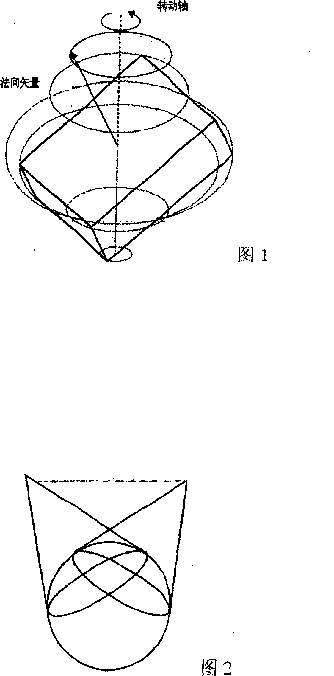
[0050] Determine the spatial position of the rotating body.

[0051] When determining the spatial position of a rotation, especially of a rotationally symmetric body on which no targets or markers are used and which has no traceable point from the start, the following methods and way to obtain local geometry details. By means of an arithmetic reconstruction of a preferred perspective image of the body, one can determine the unique geometrical details (eg points, edges, surfaces) of the body of revolution in space. One tracks the unique geometry details during the subject's rotation. The 3D point then moves on a circular orbit in space, with the edges and surface target lines forming the surface of revolution around the actual axis of rotation.

[0052] For this purpose, a preferably parametric 3D model is firstly used, which forms a good localizable part of the actual geometry of the rotating body. For example, the 3D model can be a cube, a cylinder, a circular surface, or ...


PUM


Abstract

The invention relates to a method and unit for determining the spatial position of a wheel rim relative to a measuring unit having at least one camera, the wheel rim being located within the field of vision of the camera. This method involves: the provision of a model that describes, by means of model parameters, a model body of a localizable geometrical detail of the wheel rim and the spatial position of the model body relative to the measuring unit; the recording of an image of the geometrical detail of the wheel rim by using the camera; adapting the image of the model body, which results from the model parameters, to the image of the geometrical detail of the wheel rim by modifying model parameters of the model, and; tracking the modifications of the model parameters of the model during the adaptation. The data concerning the position of the model body of the geometrical detail of the wheel rim represent the spatial position of the geometrical detail of the wheel rim and thus the wheel rim itself when the image of the model body of the geometrical detail of the wheel rim resulting from the model parameters corresponds with the recorded image of the geometrical detail of the wheel rim within predetermined tolerance limits. The invention also relates to a method for measuring a chassis and to a chassis measuring device that uses said method and said unit.

Description

technical field [0001] The invention relates to a measuring method and a measuring device for determining the spatial position of a wheel rim relative to a measuring device comprising at least one camera, wherein the wheel rim is located in the field of view of the camera, as well as a wheel alignment measuring method and a wheel alignment measuring system, wherein , using this type of measurement setup. Background technique [0002] In DE 100 43 354.5, a wheel alignment measuring system with measuring heads is disclosed, which is used for determining the wheel position of a motor vehicle at a measuring location, wherein each measuring head has at least one camera, which are arranged for measuring the alignment An object in the field of view of a camera and positioned in a fixed relationship relative to a wheel of a motor vehicle, wherein the image of the camera can be evaluated by an evaluation device in order to determine the spatial position of the measurement space posit...

Claims


Application Information

Patent Timeline
Patent Type & Authority Patents(China)
IPC IPC(8): G01B11/275
CPCG01B2210/14G01B11/2755
Inventor 卡林·多纳赫曼·布克斯斯德梵·斯考莫鲁道夫·英格
Owner BEISSBARTH
Why Eureka
Try Eureka