Electromagnetic stove

An induction cooker, electromagnetic technology, applied in the field of induction cooker, can solve the problems of messy panel design, inconvenient operation and use, unsightly, etc., to achieve the effect of simple and beautiful design, convenient operation and use

Inactive Publication Date: 2008-02-27
FOSHAN FUSHIBAO ELECTRICAL APPLIANCE TECH
View PDF4 Cites 0 Cited by
  • Summary
  • Abstract
  • Description
  • Claims
  • Application Information

AI Technical Summary

Problems solved by technology

[0004] The shortcomings of the above-mentioned LED indication method are: (1) It is very inconvenient to operate and use
Since the brightness of the LED is not very high, and the common colors are only red, green, yellow, etc., when the ambient brightness is high, or when operating under light, especially when operating under a light source with a certain color temperature , the colors are not only indistinguishable, but even illegible
In this way, the difficulty of operating the user is increased, and it is very inconvenient to use
(2) The panel design is messy
Modern induction cookers often have multiple functions and working states, such as various cooking methods, various power options, and various heating times. If one LED is used to indicate, there will be many LEDs on the panel of the induction cooker, which not only takes up space, but also makes the panel design very messy and unsightly
[0005] The liquid crystal digital indication method also has the defect of being unclear when the ambient brightness is high, or when operating under light, especially when operating under a light source with a certain color temperature; at the same time, the liquid crystal often works on high-temperature objects. around, its service life will be greatly shortened

Method used


Image

  • Electromagnetic stove

Examples


Embodiment 1

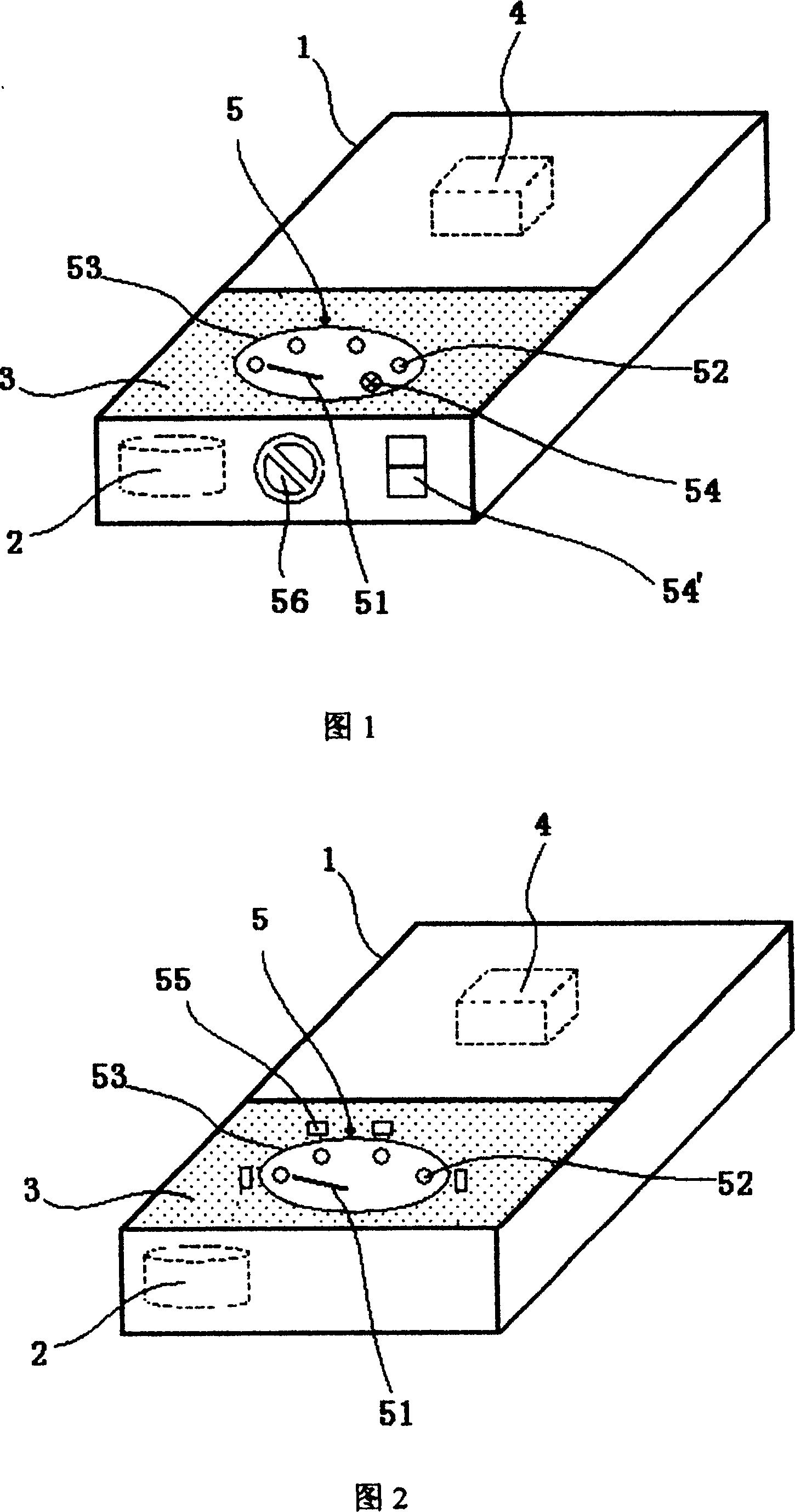
[0031] As shown in FIG. 1 , an electromagnetic oven includes an oven body 1 , an electromagnetic heating element 2 , a functional panel 3 and a control circuit 4 . An electromagnetic heating element 2 and a control circuit 4 are arranged in the furnace body 1 , and a functional panel 3 is arranged on the upper surface of the furnace body 1 . The function panel 3 is provided with a pointer-type function indicating device 5; the control circuit 4 is electrically connected with the pointer-type function indicating device 5.

[0032] The pointer-type function indicating device 5 mainly includes a pointer 51 that can rotate around a fixed axis, various function indicating positions 52 and a dial 53. In this embodiment, the shape of the dial 53 is circular. The pointer 51 of the pointer-type function indicating device 5 rotates around a fixed axis, the fixed axis is located below the center of the dial 53, and the function indicating positions 52 are evenly distributed around the in...

Embodiment 2

[0038] As shown in FIG. 2 , the main difference from Embodiment 1 is that the control knob 56 is omitted, and the control knob 56 is used to control the control circuit 4 and the pointer-type function indicating device 5 with a tact switch 55 . At the position corresponding to each function indication position 52, a tact switch 55 is arranged, the tact switch 55 is electrically connected with the control circuit 4, the tact switch 55 is fixed on the periphery of the dial 53, the tact switch 55 and the corresponding function indication position 52 are all on the radial extension of the pointer 51. During use, press tact switch 55, transmit signal to control circuit 4, control circuit 4 drives the pointer 51 of pointer type function indicating device 5 to rotate and indicate to the function indication position 52 corresponding to this tact switch 55, the user can conveniently Observing the working state of the induction cooker at this time will not cause misidentification.


PUM


Abstract

The invention discloses an electromagnetic oven. It includes oven body, electromagnetic heater, face plate, and control circuit. The heater and control circuit are set in the oven body. And the face plate is set on its surface. And the face plate is set pointer type indicating device. And the device includes rotatable pointer, different indicating places, and dial plate. The control circuit is electrically connected with the indicating device. It has the advantages of convenient using, high reliability, and wild application, and so on.

Description

technical field [0001] The invention relates to an electromagnetic cooker. Background technique [0002] The induction cooker generates an alternating magnetic field through an electronic control circuit and an electric coil. When the bottom of the iron pot is placed on the furnace surface, the pot cuts the alternating magnetic force line and generates an alternating current (ie eddy current) at the metal part of the bottom of the pot. , The eddy current makes the iron molecules of the pan move at high speed and irregularly, and the molecules collide and rub against each other to generate heat energy. It has the advantages of fast heating, high thermal efficiency, no open flame, no smoke, no harmful gas, no heat radiation to the surrounding environment, small size, and safety. With the advantages of good performance and beautiful appearance, it can complete most of the cooking tasks in the family. People call it "the god of cooking" and "green stove". [0003] On the contr...

Claims


Application Information

Patent Timeline
Patent Type & Authority Patents(China)
IPC IPC(8): F24C7/00H05B6/12
Inventor 陆社本刘翔高
Owner FOSHAN FUSHIBAO ELECTRICAL APPLIANCE TECH
Why Eureka
Try Eureka