Monitoring diagnosis device of computer main board failure

A diagnostic device and motherboard technology, applied in the detection of faulty computer hardware, hardware monitoring, etc., can solve problems such as high cost, waste of resources, and user complaints, and achieve the effect of simple circuit composition, simple installation, and reduced trouble

Inactive Publication Date: 2008-03-12
LENOVO (BEIJING) LTD
View PDF6 Cites 0 Cited by
  • Summary
  • Abstract
  • Description
  • Claims
  • Application Information

AI Technical Summary

Problems solved by technology

[0008] As far as the first way is concerned, users may be able to tolerate it once in a while, but if the frequency is more, it is easy for users to complain, and at the same time form a bad impression of the company's after-sales service
[0009] Although the second way can reduce the troubles of users, it is a huge waste of resources for computer companies.
[0012] But this fault detection card has some deficiencies: at first, because this fault detection card only processes the detection signal that BIOS internal program produces, therefore can't detect the fault situation until the BIOS starts normally after starting the computer; secondly, because this fault The detection card obtains the detection signal through the PCI or ISA slot, so it generally needs to be installed inside the chassis, that is to say, the chassis must be opened to insert the card into the slot to display the detection results, which is obviously unrealistic for users ; Again, because this fault detection card needs to obtain detection signal by PCI or ISA slot, therefore, must be provided with I / O address decoder, code latch, code decoding driver etc., its cost is higher and working process is relatively complex
[0013] In addition, there are still some monitoring devices with small LCD screens in the prior art. Although the user does not need to open the case, due to the high cost, it is generally only equipped on the server. It is difficult for ordinary home computer users to accept its high price.
Moreover, the monitoring device cannot detect the fault condition from the time the server is turned on until the BIOS starts normally.

Method used


Image

  • Monitoring diagnosis device of computer main board failure
  • Monitoring diagnosis device of computer main board failure
  • Monitoring diagnosis device of computer main board failure

Examples


Embodiment Construction

[0051] When the computer is turned on, the monitoring and diagnosing device for the fault of the computer main board of the present invention can intuitively know the operating state and fault information of the computer main board, so that even when the display does not show, it can also monitor the hardware fault and record its fault information, so as to It is convenient for users and maintenance personnel to grasp the cause of the failure in time.

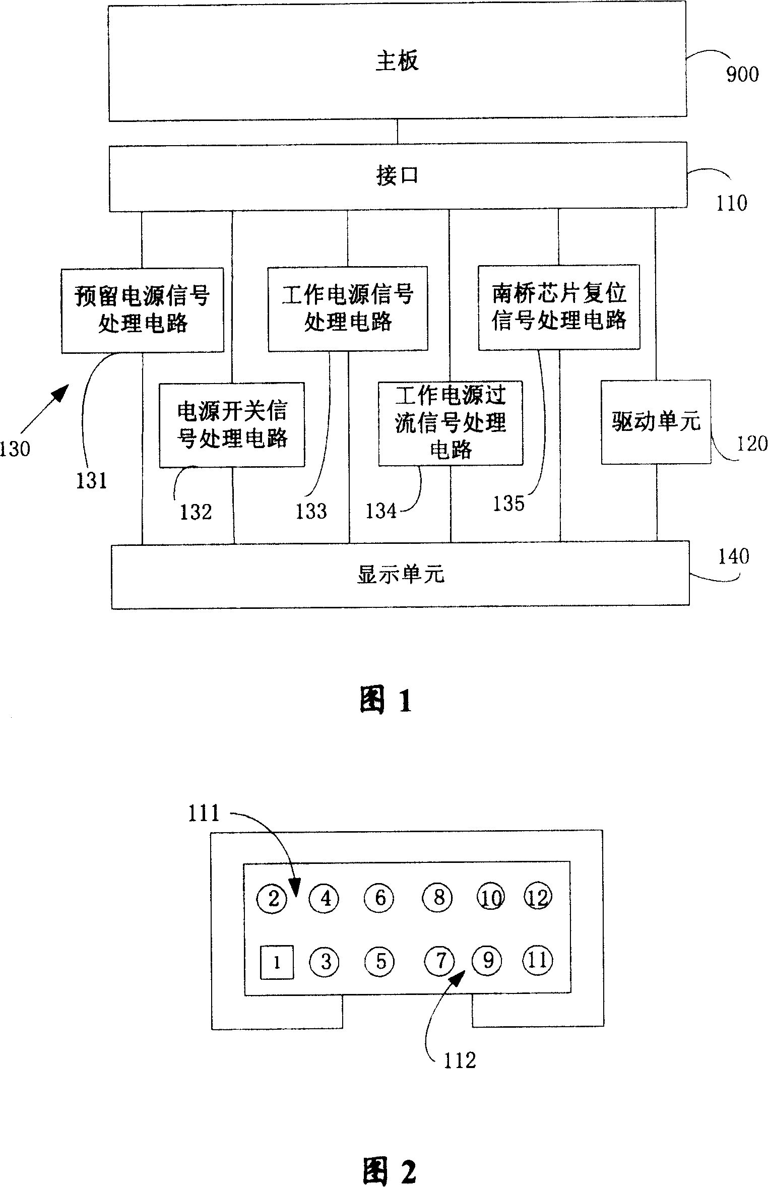
[0052] Please refer to Fig. 1, which is a functional block diagram of a monitoring and diagnosing device for a computer motherboard failure of the present invention.

[0053] The monitoring and diagnosis device includes an interface 110 , a drive unit 120 , a signal processing unit 130 and a display unit 140 . The interface 110 is used to receive signals from the main board 900 and send them to the drive unit 120 or the signal processing unit 130, and the display unit 140 displays the operating status and fault information of t...


PUM


Abstract

The present invention discloses a monitoring diagnostic device of computer main-broad fault. It includes the following components: display unit for displaying running state of the described computer main board in the process of starting computer; first interface for obtaining electrically computer-starting time-sequence signal of computer main board from the computer main board; and signal processing unit for receiving the above-mentioned time-sequence signal and converting it into display unit drive signal to drive display unit.

Description

technical field [0001] The invention relates to the field of computer fault detection and maintenance, in particular to a monitoring and diagnosing device for computer motherboard faults. Background technique [0002] With the development of information technology, the application of computers is becoming more and more extensive, which brings great convenience to people's work, study and life. However, computer failures are inevitable. In order to maintain in time, it is necessary to correctly locate the cause of the failure. [0003] As we all know, during the boot process of the computer, some detection and monitoring circuits on the motherboard itself can detect the voltage and temperature on the motherboard, and at the same time, the BIOS (basic input and output system) monitors the CPU (central processing unit), memory, hard disk and Identify the model of the external card and detect its working status. And all the detected information will be recorded, and then displ...

Claims


Application Information

Patent Timeline
Patent Type & Authority Patents(China)
IPC IPC(8): G06F11/32G06F11/22
Inventor 何彦安岩
Owner LENOVO (BEIJING) LTD
Why Eureka
Try Eureka